
Spectroelectrochemistry Raman
Raman spectroelectrochemistry combines electrochemical control, Raman microscopy and spatial mapping to monitor molecular and structural changes during redox reactions. The L215, O215 and C215 systems share an integrated three-electrode and Raman platform but use different motorised XYZ stages. Researchers can select the appropriate model according to mapping resolution, positioning accuracy, travel range and the need for closed-loop stage control.

L215 Integrated Raman Spectroelectrochemistry Microscope
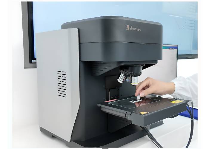
O215 Integrated Electrochemical Raman Microscope
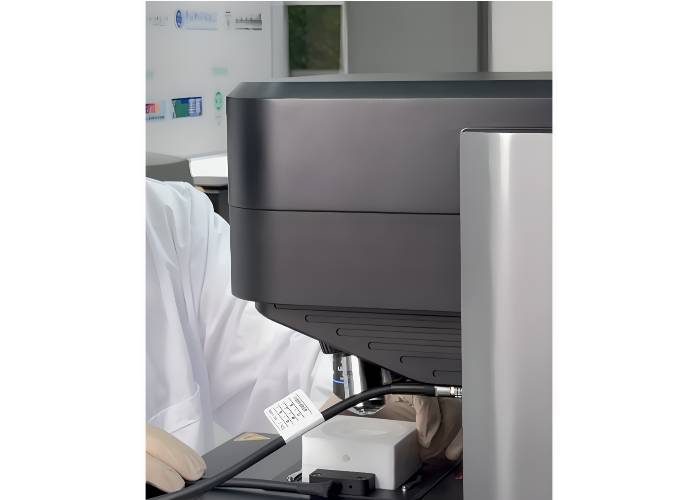
C215 Integrated Electrochemical Raman Microscope
Spectroelectrochemistry Raman
Raman spectroelectrochemistry combines controlled electrochemical measurements with Raman spectroscopy to monitor molecular, structural and interfacial changes as a reaction occurs. It enables researchers to associate Raman bands directly with applied potential, current, time and spatial position. The L215, O215 and C215 integrated systems combine Raman microscopy, electrochemical control and automated mapping within one coordinated platform, with the motorised XYZ stage providing the principal distinction between the three configurations.
Overview
Conventional electrochemical measurements show how current responds to potential or time, but they may not directly identify the molecular species, surface intermediates or structural transformations responsible for that response.
Raman spectroscopy provides a vibrational fingerprint of molecules and materials. When Raman measurements are collected during an electrochemical experiment, researchers can follow changes in chemical bonding, oxidation state, crystal phase, surface adsorption and electrode structure under controlled electrochemical conditions.
A Raman spectroelectrochemistry experiment may therefore provide complementary information about:
- The potential at which a molecular or structural transformation begins
- The formation and disappearance of reaction intermediates
- Changes in catalyst oxidation state or crystal structure
- Adsorption and desorption at an electrode–electrolyte interface
- Battery electrode and electrolyte-interface evolution
- Corrosion products and passive-film formation
- Spatial variations across particles, coatings and heterogeneous electrodes
- Reversible and irreversible changes during cycling or potential stepping
Why Use an Integrated Raman–Electrochemical System?
A modular experiment may require a separate Raman microscope, potentiostat, spectroelectrochemical cell and multiple control programs. This can make sample positioning, triggering, cabling and electrochemical–spectroscopic data correlation more difficult.
The integrated L215, O215 and C215 systems combine:
- Upright reflected-light microscopy
- Raman spectral acquisition
- Automated Raman mapping
- Three-electrode electrochemical control
- A matched magnetic spectroelectrochemical cell
- Microscopic imaging
- Synchronised Raman and electrochemical triggering
- Combined control and analysis software
Raman spectra can be associated with potential, current, time and sample position. This is useful for both steady-state measurements and transient experiments in which the spectrum evolves during a potential scan, potential step or other electrochemical sequence.
Available Raman Spectroelectrochemistry Systems
L215 Integrated Raman Spectroelectrochemistry Microscope
The L215 is the standard motorised open-loop configuration. It provides an XYZ travel range of at least 60 × 60 × 30 mm, specified stage accuracy of ±3 µm and Raman mapping resolution better than 2 µm. It is suitable for laboratories requiring integrated Raman microscopy, electrochemical control and routine automated mapping without the higher-precision stage configuration used in the O215 and C215.
O215 Integrated Electrochemical Raman Microscope
The O215 uses a German-made, high-precision motorised open-loop XYZ stage. It provides at least 75 × 50 × 50 mm travel, a specified minimum stage increment of no more than 0.01 µm, ±3 µm stage accuracy and Raman mapping resolution better than 1 µm. It is suited to experiments requiring finer mapping and a larger vertical travel range while retaining open-loop stage control.
C215 Integrated Electrochemical Raman Microscope
The C215 uses a German-made, high-precision closed-loop XYZ translation stage. Its position-feedback system provides at least 75 × 50 × 50 mm travel, a specified minimum stage increment of no more than 0.05 µm, ±1 µm accuracy and Raman mapping resolution better than 1 µm. It is intended for demanding mapping workflows requiring improved positioning accuracy and reliable return to defined coordinates.
Compare the L215, O215 and C215
| Selection attribute | L215 | O215 | C215 |
|---|---|---|---|
| Motorised stage type | Standard open-loop XYZ stage | High-precision open-loop XYZ stage | High-precision closed-loop XYZ stage |
| Position feedback | Open-loop operation | Open-loop operation | Closed-loop position feedback |
| XYZ travel range | ≥60 × 60 × 30 mm | ≥75 × 50 × 50 mm | ≥75 × 50 × 50 mm |
| Minimum commanded increment | 0.25 µm at 20 microsteps; 5 µm full step | ≤0.01 µm | ≤0.05 µm |
| Specified stage accuracy | ±3 µm | ±3 µm | ±1 µm |
| Raman mapping resolution | Better than 2 µm | Better than 1 µm | Better than 1 µm |
| Coordinate-repeatability approach | Standard open-loop positioning | Fine-increment open-loop positioning | Feedback-corrected closed-loop positioning |
| Practical selection fit | Routine integrated Raman mapping and electrochemical analysis | Finer mapping and expanded XYZ travel | Higher-accuracy mapping and repeatable coordinate positioning |
| Typical user | General research and teaching laboratories | Advanced materials and interface-research laboratories | Laboratories requiring demanding automated mapping and position control |
The minimum commanded stage increment is not the same as the achievable Raman spatial resolution. Raman imaging performance also depends on the laser wavelength, objective numerical aperture, optical configuration, sample properties and signal-to-noise ratio.
Shared Platform Specifications
The three models use a common Raman microscope and electrochemical platform. Their main technical difference is the motorised translation stage.
| Shared parameter | Configured specification |
| System architecture | Integrated Raman microscope, mapping platform and three-electrode electrochemical module |
| Microscope | Upright reflected-light microscope with LED bright-field illumination |
| Imaging camera | 8 MP high-resolution camera |
| Objective turret | Five-position manual turret |
| Supplied objectives | 10×, 50× and 100× |
| 10× objective | NA 0.30; working distance 8.5 mm |
| 50× objective | NA 0.75; working distance 3.0 mm |
| 100× objective | NA 0.90; working distance 1.0 mm |
| Confocal rejection | Slit-based optical rejection; no physical confocal pinhole |
| Excitation options | 532, 633 or 785 nm |
| 532 nm configuration | TEM₀₀ laser, ≥100 mW; spectral range 170–3900 cm⁻¹ |
| 633 nm configuration | TEM₀₀ laser, ≥30 mW; spectral range 170–3900 cm⁻¹ |
| 785 nm configuration | TEM₀₀ laser, ≥100 mW; spectral range 170–3400 cm⁻¹ |
| Grating | Rotatable 1800 grooves/mm grating |
| Spectral resolution | Better than 4 cm⁻¹ with the specified 1800 grooves/mm grating |
| Detector cooling | Two-stage cooling to below −20 °C |
| Specified signal-to-noise ratio | 5000:1 |
| Electrochemical configuration | Three-electrode operation |
| Applied voltage range | ±10 V |
| Voltage accuracy | 0.1% of full scale ±1 mV |
| Potential measurement deviation | 0.2% of full scale ±2 mV |
| Applied current range | ±250 mA |
| Applied current accuracy | 0.1% of full scale |
| Current measurement deviation | ±0.2% of full scale |
| Reference-electrode input impedance | >1 × 10¹² Ω |
| Raman–electrochemical trigger delay | ≤100 ns |
| Data export | CSV and TXT |
| External control | Basic HTTP-based control interface |
| Nominal dimensions | 33 × 62 × 48 cm |
| Built-in EIS | Not supported; external EIS-capable potentiostat required |
Specifications should be confirmed in the final quotation because laser, stage, electrochemical cell and software requirements may vary with the selected configuration.
Magnetic Spectroelectrochemical Cell
The integrated systems use a matched magnetic spectroelectrochemical cell designed to simplify connection to the internal electrochemical module.
The cell incorporates:
- A sealed cell body for the electrolyte or reaction solution
- An electrical interface base
- A central working-electrode position
- Counter- and reference-electrode connections
- A magnetic connection to the instrument sample-stage base
The magnetic interface reduces loose cabling around the optical measurement region and helps maintain a consistent connection between the cell and integrated electrochemical module.
Verified working-electrode formats include:
- Standard disc electrodes
- Flat round or square metal plates
- Glassy carbon disc electrodes
- Carbon paper
Liquid flow-through operation can also be supported. Foams, gas-diffusion electrodes, battery electrodes, membrane assemblies, powders on substrates, thin films and sealed gas-controlled measurements should be reviewed before ordering because suitability depends on electrode geometry, cell sealing, optical access and objective working distance.
How to Choose the Right Model
Start with the sample, measurement objective and required mapping performance.
Choose the L215 when the primary requirement is an integrated Raman–electrochemical platform with motorised mapping for routine point analysis, time-series measurements and chemical imaging. Its standard open-loop stage provides broad lateral travel and mapping resolution better than 2 µm.
Choose the O215 when finer Raman mapping, increased vertical travel and very small programmed stage increments are required. Its high-precision open-loop stage is suitable for heterogeneous catalysts, particles, coatings and materials where submicrometre-class mapping performance is valuable, but closed-loop position feedback is not essential.
Choose the C215 when positioning accuracy and reliable return to defined coordinates are central to the experiment. Its closed-loop stage corrects position using feedback and provides specified accuracy of ±1 µm. This can be advantageous for repeated mapping, automated particle workflows, long-duration experiments and measurements that revisit selected regions after electrochemical changes.
Before quotation, also confirm:
- Required laser wavelength
- Expected fluorescence
- Sample-heating sensitivity
- Raman spectral range
- Objective working distance
- Electrochemical cell geometry
- Electrode format
- Need for EIS
- Flow, gas or sealed operation
- Glovebox installation requirements
- Laser-safety and electrical-compliance requirements
Selecting the Raman Excitation Wavelength
The three models can be configured with 532, 633 or 785 nm excitation.
532 nm generally provides stronger Raman scattering and is commonly used for inorganic materials, carbon structures, catalysts and many electrode materials. However, some samples may fluoresce or absorb strongly at this wavelength.
633 nm provides an intermediate excitation option and may offer a useful balance between Raman intensity, fluorescence and material absorption.
785 nm is commonly selected to reduce fluorescence from organic materials, polymers, biological samples and some complex electrode systems. Raman scattering is generally weaker at longer wavelengths, and the configured spectral range is 170–3400 cm⁻¹ rather than 170–3900 cm⁻¹.
Sample testing is recommended when the most suitable excitation wavelength is uncertain.
Typical Applications
Raman spectroelectrochemistry can support:
- Hydrogen evolution reaction studies
- Oxygen evolution and catalyst-reconstruction research
- Electrochemical carbon dioxide reduction
- Battery electrode and electrolyte-interface analysis
- Solid-electrolyte interphase formation studies
- Electrolyte decomposition and degradation monitoring
- Corrosion-product and passive-film analysis
- Conducting polymers and electrochromic materials
- Carbon materials, graphene and other two-dimensional materials
- Surface adsorption and molecular-film studies
- Catalyst-particle and heterogeneous-electrode mapping
- Electrochemical sensor and biosensor-interface research
- Potential-dependent phase and oxidation-state transformations
Integration and Compatibility
The integrated electrochemical module supports three-electrode operation but does not presently include electrochemical impedance spectroscopy.
Researchers requiring EIS can use an appropriate external potentiostat or galvanostat, subject to confirmation of cell connections, synchronisation and experimental workflow.
Alternative sample geometries or modular experiments may require a specialised in-situ or operando electrochemical cell. Researchers comparing an integrated platform with a modular Raman arrangement may also review available laboratory Raman systems.
Compatibility should be assessed across the complete setup, including:
- Potentiostat connections
- Working, reference and counter electrodes
- Optical-window material
- Microscope-objective working distance
- Electrolyte compatibility
- Cell sealing
- Gas or liquid flow
- Software triggering
- Glovebox access
- Laser-safety controls
Safety and Operating Considerations
The available laser sources are Class 3B. The final instrument configuration must be reviewed against the laboratory’s laser-safety procedures and applicable Australian or New Zealand requirements.
Before installation, confirm the required:
- Laser enclosure and access controls
- Key switch or interlock arrangement
- Laser eyewear and optical-density rating
- Warning labels and emission indicators
- Emergency and shutdown procedures
- Electrical and electromagnetic-compliance documentation
- Ventilation and thermal management
- Glovebox cable routing and service access
The standard system should not be assumed to include every institutional laser-safety feature. Required controls and documentation should be confirmed before quotation and installation.
Why Source Through ScienceGears?
ScienceGears supports researchers across Australia and New Zealand with model selection, Raman-wavelength assessment, cell and electrode configuration, external potentiostat integration, installation planning and quotation preparation.
Support can also include sample-trial discussions, commissioning guidance, user training and troubleshooting for the combined Raman, electrochemical and mapping workflow.
Frequently Asked Questions
What is Raman spectroelectrochemistry?
Raman spectroelectrochemistry records Raman spectra while the potential or current of an electrochemical sample is controlled. It allows spectral changes to be correlated with electrochemical conditions, helping researchers identify reaction intermediates, structural changes, surface species and electrode transformations during an experiment.
What is the main difference between the L215, O215 and C215?
The three systems share the same basic Raman microscope, laser options, electrochemical module and software platform. Their principal difference is the motorised XYZ stage. The L215 uses a standard open-loop stage, the O215 uses a higher-precision open-loop stage, and the C215 uses a closed-loop stage with improved specified positioning accuracy.
Which model is best for Raman mapping?
The appropriate model depends on the required mapping resolution and position control. The L215 supports mapping resolution better than 2 µm. Both the O215 and C215 are specified for mapping resolution better than 1 µm. The C215 additionally provides closed-loop feedback and ±1 µm specified stage accuracy for demanding coordinate-repeatability requirements.
Which excitation wavelength should I choose?
Select the wavelength according to the sample’s Raman response, fluorescence, absorption and susceptibility to laser heating. A 532 nm laser often provides stronger Raman scattering, 633 nm provides an intermediate option, and 785 nm commonly reduces fluorescence. Testing a representative sample is recommended when the optimum wavelength is uncertain.
Does the built-in electrochemical module support EIS?
No. The integrated module supports three-electrode electrochemical operation but does not presently provide electrochemical impedance spectroscopy. Researchers requiring EIS should select an appropriate external potentiostat or impedance analyser and confirm the required cell connections and synchronisation workflow.
Is the microscope a true pinhole-confocal Raman microscope?
The optical system provides slit-based confocal rejection but does not use a physical confocal pinhole. This distinction should be considered when comparing the system with pinhole-confocal Raman microscopes or when a particular confocal architecture is required by the experiment.
Can the systems be installed in a glovebox?
The compact integrated design can be considered for glovebox installation. However, available space, heat dissipation, cable routing, vibration, service access, cell handling and Class 3B laser-safety controls must be evaluated before installation. The complete configuration should be reviewed against the specific glovebox and institutional requirements.
What support is available in Australia and New Zealand?
ScienceGears can assist with model and wavelength selection, cell and electrode compatibility, external potentiostat requirements, sample-trial discussions, quotation preparation, installation planning, commissioning guidance, training and troubleshooting. Providing details of the sample, electrochemical method, mapping requirement and operating environment helps identify the most appropriate configuration.
Contact ScienceGears to discuss your sample, electrochemical method, Raman wavelength, mapping requirements, cell geometry and installation environment, or to request a quotation for the L215, O215 or C215 system.