

This guide explains how to select an appropriate counter electrode format for your electrochemical measurement. It covers platinum wire, helix, mesh, gauze and plate formats, together with graphite rod and carbon cloth; indicative, model-dependent specifications; practical area and compliance checks; contamination pathways that can bias sensitive measurements; material-appropriate cleaning guidance; and the factors that determine whether a platinum or carbon-based counter electrode is suitable.
Table of contents
- Why the counter electrode is underspecified in most published methods
- The role of the counter electrode — what it actually does in a three-electrode cell
- The area ratio rule — sizing your counter electrode correctly
- Platinum wire and helix wire — the compact default
- Platinum mesh — for low current density and uniform distribution
- Platinum gauze — for electrosynthesis and high-current applications
- Platinum plate — for flat geometry and corrosion applications
- Graphite rod — the cost-effective alternative
- Carbon cloth — for flow cells and gas-evolving systems
- Current distribution and geometry — positioning matters
- Contamination mechanisms and how to prevent them
- Cleaning protocols for each counter electrode material
- When graphite is acceptable — and when it is not
- Application decision matrix
- Frequently Asked Questions
- Expert support — how ScienceGears works alongside your research
1. Why the counter electrode is underspecified in most published methods
Open any electrochemistry methods section and you will find precise descriptions of the working electrode — material, diameter, polishing procedure, modification protocol — alongside equally careful specification of the reference electrode: type, filling solution, junction potential, calibration method. The counter electrode, by contrast, is typically described as "a platinum wire" or "a graphite rod" with no further detail.
This informality persists because the counter electrode appears to be passive — it completes the circuit but does not participate directly in the measurement. That impression is partly correct and mostly misleading. The counter electrode's surface area relative to the working electrode determines whether the cell can pass the required current without excessive overpotential. Its material determines whether dissolution products or catalytic intermediates from the counter electrode reaction contaminate the working electrode electrolyte. Its geometry relative to the working electrode determines the uniformity of the current distribution across the working electrode face — a variable that directly affects the quality of thin film deposition, bulk electrolysis yield, and the shape of fast-scan voltammetry.
Getting the counter electrode right is the difference between a cell that limits your working electrode measurement and one that is genuinely invisible in the data. This guide gives you the information to make that specification correctly the first time, across every counter electrode format available through ScienceGears.
The role of the counter electrode — what it actually does in a three-electrode cell
In electrochemical measurements, the working electrode is where redox reactions of interest occur. The counter, or auxiliary, electrode completes the current circuit while ideally minimising chemical interference with the working-electrode measurement.
In a potentiostatically controlled three-electrode cell, the potentiostat controls the potential difference between the working electrode and the reference electrode by passing current between the working electrode and the counter electrode. The reference electrode carries virtually no current — it is a potential reference only. The counter electrode carries all of the current that flows through the working electrode. The counter reaction depends on the electrolyte, dissolved species, current direction and counter-electrode potential. In aqueous media it may involve hydrogen or oxygen evolution, but oxidation or reduction of other electrolyte components can dominate.
The suitability of the counter electrode must also be considered alongside the current range and compliance voltage of the control instrument. Browse the full Potentiostats and Galvanostats range.
Three properties of the counter electrode directly affect the working electrode measurement:
- Surface area: The counter electrode's area determines the maximum current density it must sustain whilst passing the current generated at the working electrode. For a given cell current, counter-electrode area helps determine its current density. If the available area or counter reaction is inadequate, counter-electrode polarisation and solution resistance may drive the potentiostat towards its compliance-voltage limit, resulting in poor potential control or additional side reactions.
- Material inertness: The counter electrode reaction produces a species at the electrode surface — a dissolved gas (H₂ or O₂), a dissolved ion, or an electrodeposited product — that may migrate through the electrolyte to the working electrode and interfere with the measurement. Platinum and graphite are preferred because they minimise this contamination, but for different reasons and with different limitations.
- Geometry and positioning: The spatial relationship between the counter electrode and the working electrode determines how uniformly the current distributes across the working electrode surface. Poor geometry — a counter electrode that is too far from the working electrode, too small, or asymmetrically positioned — creates a non-uniform current distribution that compromises electrode kinetics measurements and thin-film deposition uniformity.
3. The area ratio rule — sizing your counter electrode correctly
The counter electrode must have a large enough area to support the current conduction generated on the working electrode. As a practical starting point, use a counter electrode with an accessible area several times greater than the working-electrode area. Then verify that counter-electrode polarisation, gas evolution, solution resistance and potentiostat compliance remain acceptable at the intended current. A fixed 3–5× ratio is not universal.
Using a counter electrode that is appreciably larger than the working electrode often reduces its current density and polarisation. However, area alone does not establish suitability; counter-reaction kinetics, electrolyte conductivity, geometry, separator resistance and instrument compliance also matter. The reason for the ratio is straightforward: by making the counter electrode area significantly larger than the working electrode area, the current density at the counter electrode is substantially lower than at the working electrode. Lower current density at the counter electrode means lower overpotential at the counter electrode, which means the potentiostat has more voltage headroom available to control the working electrode potential precisely — and fewer extreme counter-electrode reactions that could produce contaminants.
Practical application of the area rule:
For a 3 mm diameter glassy carbon disc working electrode, the geometric area is approximately 7.1 mm². A 0.5 mm diameter platinum wire with 10 mm exposed length has approximately 15.7 mm² of lateral area, while 25–30 mm exposed length provides approximately 39–47 mm². A 230 mm length of 0.5 mm wire has approximately 361 mm² of lateral area before allowing for masked sections, contact points or incomplete immersion. For mesh and gauze, calculate the exposed wire area from verified mesh count, wire diameter and dimensions rather than multiplying the geometric footprint by a generic factor.
For higher-current measurements, confirm that the selected potentiostat or galvanostat can supply the required current and cell voltage without reaching its compliance limit. Browse Potentiostats and Galvanostats range.
When the area rule is most critical:
- Bulk electrolysis, where the working electrode must pass large total charge over extended time
- Fast-scan cyclic voltammetry at high scan rates, where large instantaneous currents are required
- Electrodeposition of thin films, where current uniformity determines film homogeneity
- EIS measurements in which counter-electrode impedance, cell geometry or solution resistance could contribute measurably to the spectrum
When the area rule is less critical:
- Low-current measurements using a small working electrode, provided the potentiostat remains within its compliance range and the counter reaction remains stable
- Some low-current amperometric measurements, subject to the same compliance, stability and contamination checks
4. Platinum wire and helix wire — the compact default
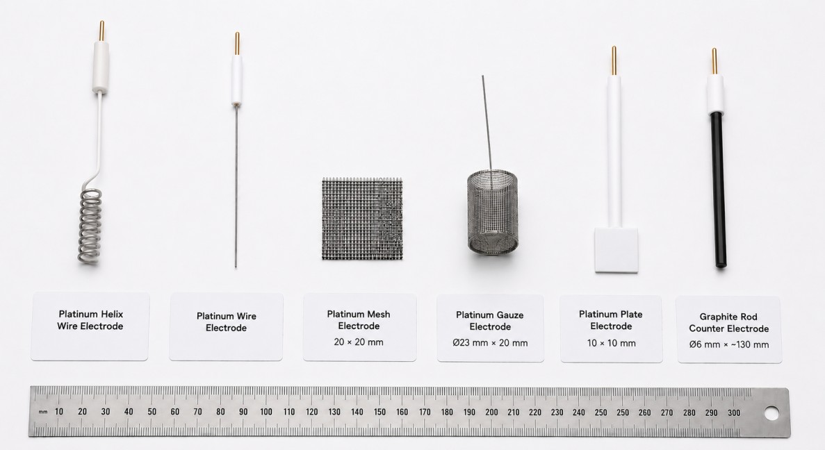
Caption: The five principal counter electrode formats stocked by ScienceGears. Selection depends on required surface area, current level, cell geometry, and contamination sensitivity of the working electrode measurement. Counter electrodes at ScienceGears →
4.1 Platinum wire — specifications
Platinum Wire: Straight wires (~0.5 mm diameter, customisable length), PTFE/glass body, with easy-connect features and standard cell compatibility.
The straight platinum wire is the simplest counter electrode format and the most widely used in routine analytical electrochemistry for two straightforward reasons: it is compact enough to fit into standard 5–50 mL electrochemical cells through a port of 3–5 mm diameter, and platinum is chemically robust in many commonly used electrolytes. However, it can oxidise, dissolve or produce soluble species under some electrolytes, counter reactions and potential histories.
Surface area of a standard Pt wire (0.5 mm Ø, 10 mm immersed length): approximately 16 mm² — equivalent to approximately 3.1–5.2 mm² of working-electrode area when a 5× to 3× initial sizing heuristic is used. This is a geometry check rather than a universal current rating. For a 3 mm Ø working electrode, a longer wire (25–30 mm immersed length) is recommended to meet the 3–5× area ratio.
4.2 Platinum helix wire — specifications
Platinum Helix Wire: PTFE-sheathed helix, ~0.5 mm diameter, ~230 mm length, coil design for high surface exposure.
The helix format coils the platinum wire into a spiral, dramatically increasing the effective surface area available within the same vertical height as a straight wire — the 230 mm total wire length packed into a helix fits in the same cell port as a 30–40 mm straight wire whilst offering more than 360 mm² of geometric surface area. This makes the helix the preferred compact format for applications where the working electrode area is moderate (3–5 mm Ø disc) but a straight wire of sufficient length would extend awkwardly beyond the cell.
The helix increases the exposed wire length within a compact volume and may improve bubble release. Any improvement in current distribution depends on its position and orientation relative to the working electrode; a side-mounted helix is not automatically more symmetric than a straight wire.
Platinum wire and helix wire →
5. Platinum mesh — for low current density and uniform distribution
5.1 Platinum mesh — specifications
Platinum Mesh: High-purity (~99.9–99.95%) mesh, wire diameters 0.1–0.5 mm, available in sizes up to 30×30 mm. Optimised for low current density.
Platinum mesh provides a large, flat electrode surface in a defined rectangular geometry. The mesh structure — an array of interlocking platinum wires with open space between them — gives mesh two advantages over a solid plate of the same external dimensions: the open structure allows electrolyte circulation through the electrode body (important in stirred systems or when gas evolution occurs at the counter electrode), and the actual electroactive surface area of the mesh wires is substantially greater than the geometric footprint of the mesh panel.
The exposed area of platinum mesh depends on its wire diameter, mesh count, woven construction, external dimensions, mounting and immersion depth. It should be calculated from those verified parameters or obtained from the supplier. The geometric footprint of a 10 × 10 mm panel is 100 mm², but its exposed platinum-wire area must not be estimated by applying a generic 3–5× multiplier.
5.2 When to choose mesh over wire
- When the working electrode is a large-area substrate (coated glass, carbon paper, large disc) requiring a counter electrode with commensurately large area to maintain the 3–5× ratio
- When current distribution uniformity across the working electrode face is important — mesh can be oriented parallel to and at a defined distance from the working electrode, giving a more symmetric field than a wire placed to one side
- When a flat, planar counter electrode is needed for flow cell or thin-layer cell geometries where the electrode-to-electrode gap is defined by the cell architecture
- For corrosion studies where the working electrode is a large flat coupon and the counter electrode should present a uniform face to it
6. Platinum gauze — for electrosynthesis and high-current applications
6.1 Platinum gauze — specifications
Platinum Gauze: Cylindrical gauze (Ø23 mm × 20 mm), 50-mesh, high surface area for electrosynthesis and energy-storage applications.
The cylindrical gauze format is specifically designed for high-current applications where neither a straight wire nor a flat mesh panel provides sufficient counter electrode area. The Ø23 mm × 20 mm dimensions describe the cylindrical envelope rather than the exposed platinum-wire area. The latter depends on the verified wire diameter, mesh count, woven structure and whether a mesh end face is present. Confirm these parameters before using the gauze dimensions in an area calculation.
The cylindrical geometry has a further advantage for electrosynthesis applications: if the working electrode is positioned axially within the cylindrical gauze, the counter electrode surrounds it on all sides, providing highly symmetric current distribution and minimising the variation in current density across different regions of the working electrode surface. This is the configuration most commonly used in preparative electrochemistry where high-purity product isolation is required and uneven current distribution would cause localised side reactions.
6.2 Platinum gauze applications
- Bulk electrolysis and preparative electrochemistry
- Electrosynthesis where high total charge must be passed at controlled potential
- Battery material characterisation at elevated current densities
- Electrochemical energy storage studies requiring extended high-current operation
7. Platinum plate — for flat geometry and corrosion applications
Platinum Plate: Flat plates (e.g., 10×10×0.1 mm), corrosion-resistant and suitable as anode/cathode in CV or bulk electrolysis.
The platinum plate format provides a defined, reproducible geometric counter electrode area in a flat planar geometry. Unlike mesh, the plate has no void fraction — the entire 10×10 mm face is solid platinum, which is relevant when the electrolyte must not circulate through the counter electrode body (for example, in flat thin-layer cells or in cells where precise geometric control of the counter-to-working electrode distance is needed for impedance measurements requiring a defined cell geometry).
A platinum plate provides a defined projected area and planar geometry. Whether it produces lower counter-electrode polarisation than a wire or mesh depends on its exposed area, surface condition, counter reaction and placement. The counter-electrode potential is not normally controlled in a standard three-electrode measurement.
Compare platinum mesh, gauze and plate formats for planar, high-area and gas-evolving cell geometries on the Counter Electrodes range page.
8. Graphite rod — the cost-effective alternative
8.1 Graphite rod — specifications
Graphite Rod: Ø3–6 mm graphite core, PTFE-sheathed, brass connector, total length ~130 mm.
The ScienceGears graphite rod counter electrode presents a graphite cylinder of 3–6 mm diameter through a PTFE sheath with a brass connector for standard cell compatibility. The graphite core is high-purity carbon — purity is the critical specification for a counter electrode graphite rod, since lower-purity graphite contains metallic impurities (iron, aluminium, vanadium, and others) that dissolve into the electrolyte under anodic or cathodic polarisation and can contaminate sensitive working electrode measurements.
Surface area of a standard graphite rod (Ø6 mm, 20 mm immersed): approximately 380 mm² — meets the 3–5× area ratio for working electrodes up to approximately 80–130 mm². This makes the graphite rod suitable as a counter electrode for most standard disc electrode and small-to-medium substrate working electrode configurations.
8.2 What graphite offers over platinum
Cost: Graphite rods are significantly less expensive than platinum in any format — the cost differential is particularly relevant for bulk electrolysis applications where the counter electrode is large and the experiment runs for many hours, representing significant continuous use of an expensive platinum electrode.
Chemical stability in alkaline and harsh media: Graphite can be useful in many neutral and alkaline systems, but it is not universally inert. Its suitability depends on whether it is anodically polarised, the electrolyte composition, current density, temperature, duration and acceptable contamination level.
Machinability: Graphite rods are readily machined and can be economical for bespoke geometries. Platinum wire and mesh can also be cut or formed, subject to the electrode construction and supplier instructions.
8.3 What graphite does not offer — and when this matters
Graphite oxidises at high anodic potentials, producing carbon dioxide and surface carbon oxides that dissolve or migrate in the electrolyte. Carbon corrosion is thermodynamically possible below the oxygen-evolution region, but its practical rate depends strongly on carbon grade, electrolyte, potential history, current density, temperature and duration. Potentials near or within the oxygen-evolution region can accelerate corrosion, but +1.0 to +1.2 V versus RHE should not be used as a universal pass/fail threshold. In experiments where the counter electrode operates well into the anodic region — high-potential bulk electrolysis, water oxidation studies, certain industrial electrochemical processes — the carbon oxidation products from a graphite counter electrode can reach the working electrode and adsorb onto its surface, altering the background current and — in catalysis studies — potentially acting as spurious co-catalysts or poisons.
This is covered in detail in Section 13 (When graphite is acceptable).
Graphite rod counter electrodes →
9. Carbon cloth — for flow cells and gas-evolving systems
Carbon cloth, carbon paper and carbon felt are related porous carbon materials but are not interchangeable. Carbon cloth is woven, whereas carbon paper is generally non-woven; their mechanical and transport properties differ. Carbon cloth is a substrate material that is cut to a desired shape and used as the counter electrode in specific cell geometries rather than a finished electrode with a PTFE sheath and connector.
Carbon cloth's most important property as a counter electrode is its combination of high surface area per unit volume, excellent electrolyte permeability, and very low flow resistance. These properties can make an appropriately selected carbon cloth a useful counter-electrode substrate in some flow-cell configurations (including CO₂ reduction flow cells, electrochemical synthesis flow reactors, and fuel cell half-cell testing), where the counter electrode must occupy a defined channel geometry, allow electrolyte to flow through it, and support gas evolution without bubble trapping.
Counter electrode use of carbon cloth — relevant applications:
- CO₂ reduction test stations where the counter electrode occupies the anode flow channel
- Three-electrode flow cells in which a verified carbon-cloth grade is used in the counter compartment and is compatible with the intended counter reaction
- Flow cell electrosynthesis reactors where a flexible, conductive, porous counter electrode is needed
- Specialised photoelectrochemical cells only when the optical transmission, chemical compatibility and electrochemical stability of the selected cloth have been verified
Key limitation: Carbon cloth shares graphite rod's carbon oxidation limitation at high anodic potential — at sustained anodic potentials above approximately +1.0 V vs RHE, carbon oxidation is a contamination concern. In applications where the counter electrode operates primarily in water oxidation (OER) conditions at strongly anodic potentials, platinum gauze or mesh is preferable.
10. Current distribution and geometry — positioning matters
The geometry of the counter electrode relative to the working electrode is the variable most consistently overlooked in three-electrode cell setup, despite having a measurable effect on the quality of voltammetric and electrosynthesis data.
10.1 The basic principle
Current flows from the working electrode to the counter electrode along the path of least resistance in the electrolyte. If the counter electrode is close to one side of the working electrode, current density is higher on the near side than on the far side — a non-uniform distribution that manifests as:
- Potential distortion or additional uncompensated-resistance effects in large-area or high-current measurements. In small analytical cells, peak broadening or asymmetry should not be attributed to counter-electrode geometry until reference drift, working-electrode fouling, adsorption, mass transport and iR effects have been excluded.
- Uneven film thickness in electrodeposition experiments
- Non-uniform passivation or activation across the working electrode face in corrosion studies
- Position-dependent EIS response in large-area working electrode measurements
10.2 Geometry rules for common cell formats
Standard cylindrical cell (5–50 mL): Position the counter electrode symmetrically around the working electrode — for a disc working electrode at the bottom of a cylindrical cell, the counter electrode should form a coaxial ring or cylinder around the working electrode axis. The platinum helix wire or cylindrical platinum gauze are the formats naturally suited to this geometry. A straight wire counter electrode should be positioned at a fixed distance from the working electrode and ideally on a circle equidistant from the disc centre, not touching the cell wall.
H-cell (H-cell configuration): The H-cell places the working and counter electrodes in separate compartments separated by a membrane. This geometry inherently limits contamination from the counter electrode to the working electrode side — any dissolution products from the counter electrode reaction are retained in the counter compartment by the membrane. This is the correct cell configuration when the counter electrode reaction is known to produce species that would interfere with the working electrode measurement (see Section 11). When using an H-cell, the counter electrode surface area should still meet the 3–5× area ratio relative to the working electrode.
Flat-cell and thin-layer cell: For flat corrosion cells or thin-layer spectroelectrochemical cells where the working electrode is a flat coupon and the cell geometry is planar, the counter electrode should be a flat mesh or plate positioned parallel to and facing the working electrode, with a defined gap. Platinum mesh (up to 30×30 mm) is the correct format for this geometry.
11. Contamination mechanisms and how to prevent them
The counter electrode preferably should not leach out any chemical substance that interferes with the electrochemical reaction or might lead to undesirable contamination of either electrode.
Counter electrode contamination reaches the working electrode by three distinct mechanisms, each requiring a different prevention strategy.
11.1 Dissolution product migration
Platinum dissolves very slightly under strongly anodic conditions, releasing Pt²⁺ or Pt⁴⁺ ions into the electrolyte. In routine CV and analytical measurements at small working electrodes with short measurement times, this dissolution is negligible. In prolonged bulk electrolysis or studies of catalysts that are sensitive to even trace platinum contamination — particularly certain non-platinum oxygen evolution or reduction catalysts — dissolved platinum ions migrate from the counter electrode to the working electrode and deposit as metallic platinum, appearing as catalytic activity that belongs to the platinum deposit rather than the studied material.
Prevention: Use a separated cell (H-cell) with the platinum counter electrode in a separate compartment connected via a membrane or salt bridge. The separator reduces bulk mixing and may limit crossover, but it must permit ionic transport to complete the circuit and does not guarantee complete exclusion of dissolved metals or reaction products. This is the recommended configuration for any catalyst study where trace platinum contamination would be indistinguishable from the catalyst's genuine activity.
11.2 Gas evolution interference
Both hydrogen evolution (at cathodic counter electrodes) and oxygen evolution (at anodic counter electrodes) produce dissolved gases that migrate through the electrolyte. Dissolved oxygen reaching a cathodic working electrode can be reduced at the working electrode surface, producing a false current contribution in the working electrode measurement that is not related to the analyte. Dissolved hydrogen reaching an anodic working electrode can oxidise, similarly producing a false signal.
Prevention:
- Purge the electrolyte with inert gas (N₂ or Ar) before and during measurements sensitive to dissolved oxygen
- Position the counter electrode so that gas bubbles evolving from its surface rise away from the working electrode, not toward it
- Use a separated cell configuration when dissolved gas contamination is a concern for quantitative measurements
11.3 Carbon oxidation from graphite counter electrodes
At anodic potentials above approximately +1.0 V vs RHE, carbon (graphite) oxidises in aqueous electrolyte, producing CO₂ and soluble carbon oxide species that migrate to the working electrode. On a working electrode surface being studied for electrocatalysis — particularly for oxygen evolution, CO₂ reduction, or nitrogen reduction — these carbon species can adsorb, alter the surface, and either poison the catalyst or, problematically, contribute their own electrochemical activity to the measurement.
Prevention: Use platinum counter electrodes when the counter electrode will operate at high anodic potentials. When graphite must be used for cost reasons, separate the counter electrode in its own compartment and replace the electrolyte in the counter compartment after each extended experiment to prevent carbon species buildup.
12. Cleaning protocols for each counter electrode material
12.1 Platinum wire, helix, mesh, gauze, and plate
Cleaning can remove some contaminants, but the correct method depends on the electrode format, construction and contaminant. Abrasive polishing is generally unsuitable for mounted wire, helix, mesh and gauze assemblies. A dull appearance or anomalous cyclic voltammograms in pure electrolytes indicate the need for cleaning.
Electrochemical cleaning should follow the electrode manufacturer's or laboratory's validated procedure. When potential cycling is appropriate, treat the platinum item as the working electrode in a separate, clean three-electrode cell. Select the electrolyte and potential limits for the specific platinum surface and actual reference electrode, and avoid unnecessarily aggressive upper potentials or prolonged gas evolution. Do not present −0.2 to +1.5 V versus RHE as a universal cleaning window or as a procedure required before every experiment.
For persistent contamination, follow a manufacturer-approved chemical-cleaning procedure under the laboratory's chemical-safety controls. Do not provide a generic concentrated-acid immersion procedure for complete mounted electrode assemblies.
For platinum mesh specifically: Avoid mechanically polishing mesh — the mesh structure makes abrasive polishing impractical and risks damaging the wire junctions. Rely on chemical and electrochemical cleaning only.
12.2 Graphite rod
Rinse with a compatible solvent and deionised water. When wiping is necessary, use a clean, lint-free material and avoid abrasion that changes the graphite surface. After each experiment, rinse the counter electrode with deionised water. For drying, using nitrogen gas is recommended — this effectively removes moisture from the porous graphite structure without introducing new impurities.
Graphite rod counter electrodes should not be electrochemically cleaned by anodic cycling in H₂SO₄ — the anodic treatment accelerates surface oxidation and increases the contamination risk. The correct cleaning protocol is mechanical and solvent-based only:
- Rinse with deionised water immediately after removing from the cell
- Wipe gently with a soft cloth moistened with ethanol to remove adsorbed organics
- Rinse again with deionised water
- Dry under a gentle nitrogen flow to remove moisture from the porous graphite structure
- Store in a clean glass tube or sealed container — do not leave exposed to laboratory air where particulate contamination can settle in the porous graphite surface
When to replace a graphite rod counter electrode: Replace the rod if it is cracked, mechanically unstable, visibly eroded or cannot be cleaned to an acceptable blank response. Colour change alone is not a reliable replacement criterion. A degraded graphite surface releases more carbon particulates and oxidation products into the electrolyte.
12.3 Carbon cloth
Carbon cloth counter electrodes used in flow cells are typically treated as consumable items and replaced when performance degrades — the difficulty of cleaning a porous, high-surface-area fabric substrate without disturbing its porosity or depositing cleaning agent residues makes regular replacement the more practical approach. Rinse with deionised water and dry under mild vacuum or nitrogen flow between experiments when reuse within the same campaign is required.
13. When graphite is acceptable — and when it is not
This is the most practically important section in this guide, and the one most often left to researcher intuition. The choice is neither "always use platinum" nor "graphite is fine" — it is specific to the applied counter electrode potential, the measurement technique, and the sensitivity of the working electrode measurement to trace contamination.
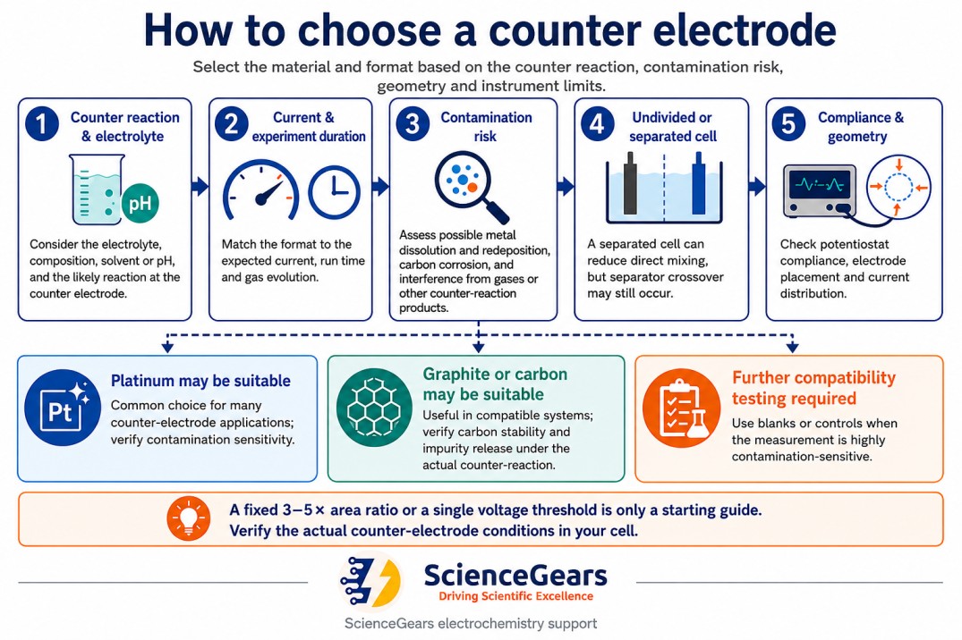
Alt text: "Two-column diagram showing conditions where a graphite rod counter electrode is acceptable versus conditions that require a platinum counter electrode, with bullet points for each."
Caption: The graphite vs platinum decision depends on the counter electrode's operating potential, the sensitivity of the working electrode measurement, and whether the cell is separated. A separated H-cell can reduce direct mixing of counter-electrode products, but separator crossover may still occur.
13.1 Conditions in which graphite may be acceptable
- Low-current, short-duration measurements may be compatible with graphite after considering the actual counter reaction and electrolyte. The working-electrode potential range alone does not establish graphite stability. For critical work, monitor or separately characterise the counter-electrode potential and inspect the counter electrolyte for corrosion products.
- Bulk electrolysis in separated cells: When the counter electrode is in its own compartment — an H-cell, a divided electrochemical cell, or any configuration with a membrane between working and counter compartments — the separated configuration reduces direct mixing of graphite oxidation products with the working-electrode electrolyte, although crossover through the separator may still occur. This makes graphite rod a cost-effective counter electrode for long-duration bulk electrolysis in separated configurations
- Teaching and screening experiments: In educational settings or in early-stage feasibility screening where the priority is a working signal rather than trace-level accuracy, graphite's lower cost and easy replaceability are legitimate advantages
- Alkaline and neutral electrolytes at low to moderate current: Graphite stability is higher in neutral to alkaline electrolyte than in strongly acidic media, and at moderate current densities the dissolution and oxidation products are minimal
13.2 Conditions in which platinum may be preferred — and where separation remains necessary
- Any catalyst study where trace platinum contamination would be indistinguishable from the catalyst's own activity: This is the most important case. If you are studying a non-platinum OER, ORR, CO₂RR, or NRR catalyst and the counter electrode is platinum, dissolved Pt²⁺/Pt⁴⁺ ions can migrate to the working electrode and deposit as metallic platinum nanoparticles — which will then contribute their own electrocatalytic activity to your measurement. The result is an inflated apparent activity for the catalyst you are studying. This contamination mechanism has been cited in the literature as the source of spurious activity in numerous published non-platinum catalyst studies. Avoid an undivided platinum counter electrode in measurements that are sensitive to trace Pt. A separated counter compartment can reduce contamination, but it may not completely prevent Pt crossover; include appropriate blanks and contamination controls.
- Counter electrode sustained above +1.0 V vs RHE: In alkaline water electrolysis anode studies, CO₂ electrolysis anode reactions, and other high-potential anodic processes, the counter electrode operates continuously in the carbon oxidation region. Platinum is required to avoid progressive contamination of the electrolyte
- Trace-level detection where carbon oxide species interfere: In certain trace analyte voltammetry measurements, the background current from dissolved carbon oxide species adsorbing on the working electrode surface is measurable. This is rare but has been documented for specific carbon-sensitive working electrode materials and buffer compositions
14. Application decision matrix
|
Application |
Recommended counter electrode |
Format |
Key rationale |
|---|---|---|---|
|
Routine CV / DPV at small disc WE (≤3 mm Ø) |
Platinum wire or helix |
Wire (0.5 mm, 25 mm+ length) or helix |
Compact; meets area ratio; fits standard cell ports |
|
Large working electrode (5–10 mm Ø disc, coated substrate) |
Platinum mesh or gauze |
Mesh 20×20 mm or cylindrical gauze |
Area ratio requires >200 mm² CE; mesh and gauze meet this |
|
Bulk electrolysis, preparative scale |
Platinum gauze |
Cylindrical Ø23 × 20 mm |
High area can be accommodated in a compact cylindrical geometry; verify actual wire area and electrode placement. |
|
EIS on coated metal |
Platinum mesh or plate |
Mesh parallel to WE |
Uniform current distribution required for clean impedance data |
|
Catalyst activity screening (non-Pt) |
Platinum (H-cell separated) or graphite (H-cell) |
Wire or helix in separate compartment |
Reduces direct crossover; does not guarantee zero Pt contamination. Use blanks and contamination controls. |
|
Cost-sensitive, low-current measurements after counter-electrode compatibility assessment |
Graphite rod |
Ø6 mm PTFE-sheathed rod |
The working-electrode potential alone does not establish graphite stability; verify the counter reaction and experiment duration. |
|
H-cell bulk electrolysis |
Graphite rod (separated) |
Ø6 mm, 20–40 mm immersed |
Separation reduces direct mixing, but separator crossover and counter-electrolyte condition must still be considered. |
|
Flat corrosion cell |
Platinum mesh |
Mesh parallel to WE coupon face |
Uniform current distribution across large flat coupon |
|
Flow cell electrosynthesis |
Carbon cloth |
Cut to channel geometry |
Permeable; handles gas evolution; low flow resistance |
|
CO₂RR or N₂RR catalyst study |
Platinum or graphite in a separated compartment, selected after contamination assessment |
Wire in separate compartment |
Both Pt dissolution and carbon corrosion can bias sensitive catalyst measurements; use separation and appropriate controls. |
|
Electrodeposition (thin film on WE) |
Platinum mesh |
Mesh parallel to WE substrate |
Uniform current distribution required for film homogeneity |
|
SPE-based measurements |
Pt wire (external) or printed CE |
External Ag/AgCl RE + external Pt CE for extended experiments |
See SPE connector guide for full detail |
|
Teaching / educational lab |
Graphite rod |
Ø3–6 mm rod |
Low cost; robust; easily replaced; adequate performance at pedagogical current levels |
All counter electrode formats are available from ScienceGears' counter electrode range with local AU/NZ stock.
15. Frequently asked questions
For broader questions about ScienceGears products, ordering, and shipping, visit our main FAQ page.
Q1. Does the counter electrode material affect the reference electrode reading?
Indirectly, yes — if the counter electrode reaction produces species that migrate to the reference electrode junction and alter the junction potential, the reference electrode reading will drift. This is most common with Ag/AgCl reference electrodes in chloride-containing electrolytes where the counter electrode reaction generates oxidised or reduced chloride species. Using a separated cell configuration — or positioning the reference electrode away from the direct diffusion path between counter and working electrode — minimises this effect. Position the reference sensing point to measure the solution potential close to the working electrode while minimising uncompensated resistance and disturbance of the current field. A Luggin capillary may be appropriate; do not apply a blanket “never between” rule.
Q2. My CV peaks are shifting between consecutive scans even though the reference electrode is stable — could the counter electrode be the cause?
Possibly, but peak drift is not diagnostic of counter-electrode contamination. Also check reference-electrode stability, electrolyte composition and pH, dissolved gases, temperature, uncompensated resistance, working-electrode conditioning, adsorption and fouling. Use blanks and controlled changes—such as replacing only the electrolyte or only the counter electrode—to isolate the cause.
Q3. How do I know if my counter electrode area is large enough for my experiment?
Calculate the exposed area for simple wire and plate geometries using their verified immersed dimensions. For woven mesh or gauze, use the verified wire diameter, mesh count, construction and exposed dimensions, or a supplier-provided area; do not apply a generic “porosity factor”. Treat an area ratio as an initial check, then confirm that the potentiostat remains within compliance and that the counter electrode does not measurably limit or contaminate the experiment at the intended current.
Q4. Can I use a stainless steel wire as a counter electrode to save cost?
Stainless steel can passivate or dissolve, particularly under anodic polarisation, and released iron, chromium or nickel species may alter the working electrode. Use it only when compatibility with the electrolyte, expected counter reaction and acceptable contamination level has been demonstrated. Platinum and graphite are commonly used alternatives, but neither is universally inert.
Q5. My platinum counter electrode has turned grey/dark and its CV in H₂SO₄ no longer shows the characteristic hydrogen peaks — what has happened and how do I recover it?
Darkening can result from adsorbates, oxide formation or deposited species, but appearance alone is not diagnostic. First rinse and inspect the electrode, then follow a manufacturer- or laboratory-approved cleaning method that is compatible with the complete assembly. Do not immerse a mounted electrode in aqua regia unless the supplier explicitly permits it and the work is covered by an institutional safety procedure. Confirm recovery using a suitable blank or control measurement; a fixed number of cleaning cycles is not a universal replacement criterion.
Q6. Should the counter electrode be immersed deeper than the working electrode in the electrolyte?
For cylindrical or standard electrochemical cells: the counter electrode active area should be fully immersed and positioned so that its active area is at the same vertical height as the working electrode active area — not significantly above or below it. If the counter electrode is positioned substantially higher or lower than the working electrode, the current distribution becomes non-uniform in the vertical direction as well as the horizontal, which is particularly problematic for large-area working electrodes or for thin-film deposition experiments where vertical uniformity of the deposited layer matters.
16. Expert support — how ScienceGears works alongside your research
Selecting a counter electrode is a decision that most researchers make once per cell design and then never revisit — until a persistent contamination issue or a non-uniform deposition result forces the question. ScienceGears stocks the complete range of counter electrode formats, and our technical team has configured three-electrode cells across the full spectrum of applications covered in this guide — from routine analytical CV to preparative electrosynthesis to sensitive non-platinum catalyst characterisation.
What expert support looks like in practice
Counter electrode selection for your specific cell geometry:
If you know your working electrode format and cell configuration but are unsure which counter electrode geometry meets the area ratio requirement and provides adequate current distribution, contact us before ordering. Describing your working electrode diameter, cell volume, and measurement technique is enough for a direct recommendation.
Talk to our technical team before ordering →
Contamination diagnosis:
If you are experiencing progressive peak shifts, increasing background current, or apparent catalyst activity that you suspect may be counter electrode contamination in origin, contact us with the cell configuration, electrolyte, working-electrode area, expected current, counter-electrode type and measurement method. A technical review of the symptom pattern and cell configuration can help narrow the likely causes and identify useful verification steps. The contamination source cannot normally be confirmed without appropriate experimental controls.
Complete three-electrode cell supply:
ScienceGears supplies components for three-electrode cell systems, subject to confirmation of compatibility with the specific cell geometry, electrolyte, current range, connector and measurement method:
- Counter electrodes — platinum wire, helix, mesh, gauze, plate, and graphite rod
- Graphite counter electrode
- Platinum mesh electrode
- Platinum wire electrode
- Reference electrodes — Ag/AgCl, SCE, RHE
- Working electrodes — disc, rod, plate, SPE formats
- Electrochemical cells — standard cylindrical, flat, jacketed
- H-cells for separated counter compartment
- Corrosion test cells — flat and jacketed
- Potentiostats and galvanostats
- Application notes
AU/NZ availability:
Selected counter-electrode formats may be available from local stock. Confirm current inventory and dispatch timing when requesting a quotation.
"The counter electrode is the one component researchers specify least carefully and replace most frequently because of contamination problems they could have prevented. Getting the area ratio, the material, and the cell separation right at the start is ten minutes of work that eliminates months of troubleshooting." — ScienceGears Technical Team
Further reading
Related ScienceGears blogs:
- Disposable sensor connector and adapter setup — making SPEs work with any potentiostat
- Screen-printed electrode guide: carbon, gold, Prussian Blue, and interdigitated sensors
Related ScienceGears resources:
- Counter electrodes — full range
- Platinum mesh electrode
- Platinum wire electrode
- Graphite rod counter electrode
- Electrochemical cells
- H-cell
- Reference electrodes
- Working electrodes — disc formats
- Potentiostats and galvanostats
- Application notes
Get in touch
Need to confirm which counter electrode format meets the area ratio requirement for your cell, or advice on separating your counter electrode to eliminate contamination? Contact our technical team — we respond within 24 hours.
Request a quote → | Counter electrodes → | About ScienceGears →