

By the end of this guide you will be able to specify the tubing, pump, reservoir and gas-routing arrangement for an MEA or flow-cell test rig, evaluate reactant-gas humidification and condensation control, carry out a leak check you can defend in a methods section, and understand the engineering checks, documentation and site-approved safety controls needed before operating with hydrogen or corrosive electrolyte.
1. Why the periphery decides the quality of your data
You have spent weeks on catalyst ink formulation, membrane pretreatment and hot-pressing. The first polarisation curve comes back noisy, the high-frequency resistance wanders by several milliohms over an hour, and a repeat run on the same MEA does not match the first. The natural suspicion falls on the MEA. In a surprising number of cases the culprit is the hardware around it: a pulsing pump, a gas line that is condensing water, a reservoir that has slowly absorbed carbon dioxide, or a fitting that weeps a few microlitres per minute.
The point is not new. Harmonised single-cell protocols for polymer electrolyte fuel cells, such as the European JRC test protocols and IEC TS 62282-7-1:2025, spend as much effort on the test station set-up, input tolerances and operating conditions as they do on the MEA itself. Their premise is that comparable results require comparable boundary conditions, and boundary conditions are set by pumps, mass flow controllers, humidifiers, heated lines and pressure control rather than by the cell.
The same logic applies to liquid-fed systems. A study of an anion exchange membrane water electrolyser, published in Membranes in 2023, examined voltage, KOH concentration and electrolyte flow rate using impedance spectroscopy. It concluded that even with symmetrical feeding of both compartments the flow rate needs to be optimised, because it influences both kinetics and cell resistance. In other words, the pump setting is an experimental variable and should be reported like one.
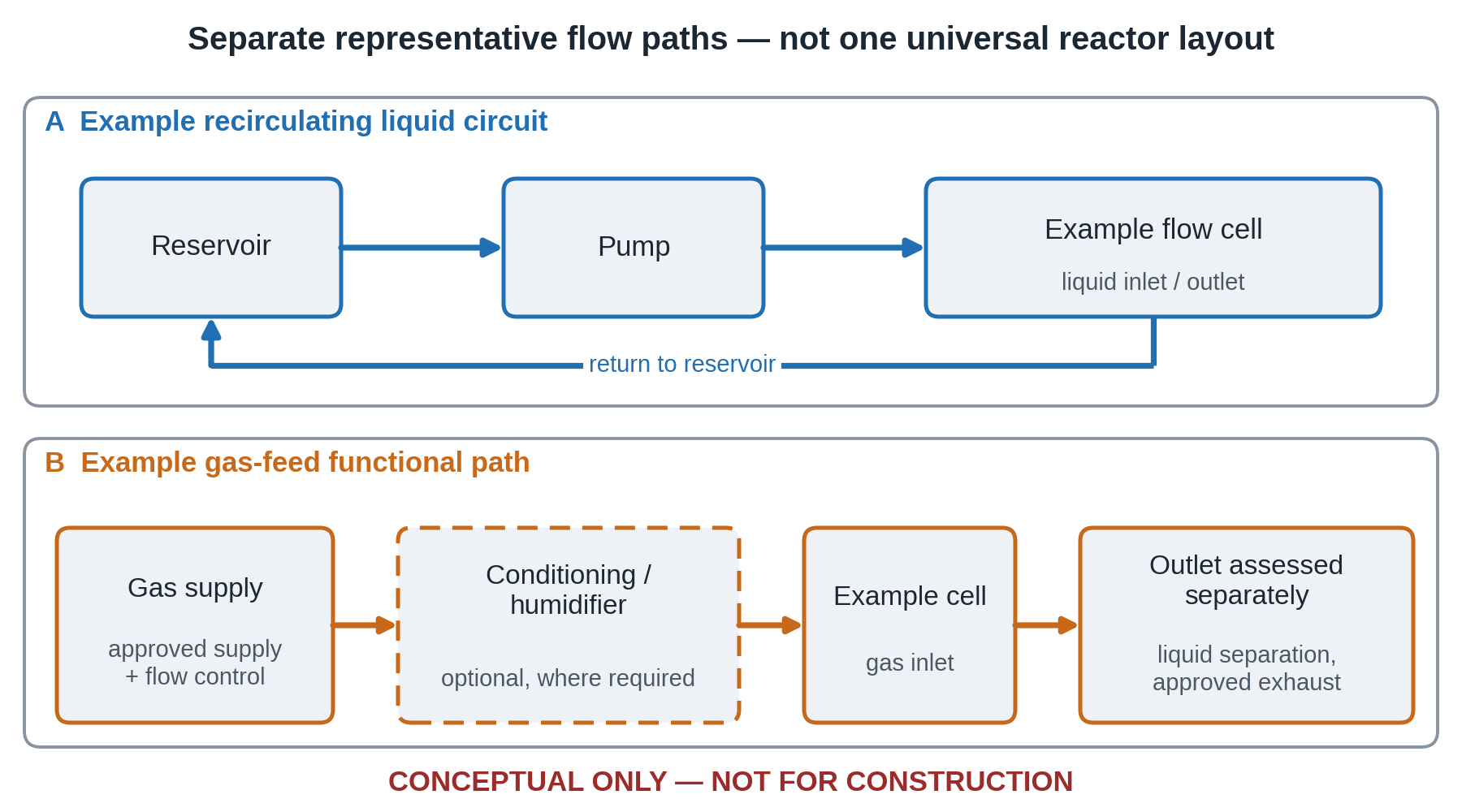
This guide treats the accessories as part of the experiment. It follows the path of a reactant from reservoir or cylinder to cell and out to the vent, and at each stage it asks the same question: what could this component change in the data, and how would you know?
Scope
The guide covers tubing, pumps, reservoirs, gas routing, humidification, leak testing and safety for MEA-based and flow-cell experiments, including electrolyser, fuel cell, CO2 reduction and redox flow configurations. It does not cover potentiostat selection, full stack design or plant-scale sizing; a note at the end of section 8 lists these as related but outside scope.
If you are still choosing the cell itself, the range of membrane electrode assembly test cells is the place to start, and the general electrochemical cell category covers the wider set of configurations. Everything that follows assumes you have a cell with defined inlet and outlet ports and want to feed it properly.
2. Tubing: choose the material by the fluid, not by habit
The problem
Tubing is usually selected from whatever is in the drawer. Soft silicone goes on because it fits a peristaltic head; clear flexible plastic goes on because you can see the bubbles. Both choices are defensible for a quick water test and both can quietly corrupt a longer experiment.
Gas permeation
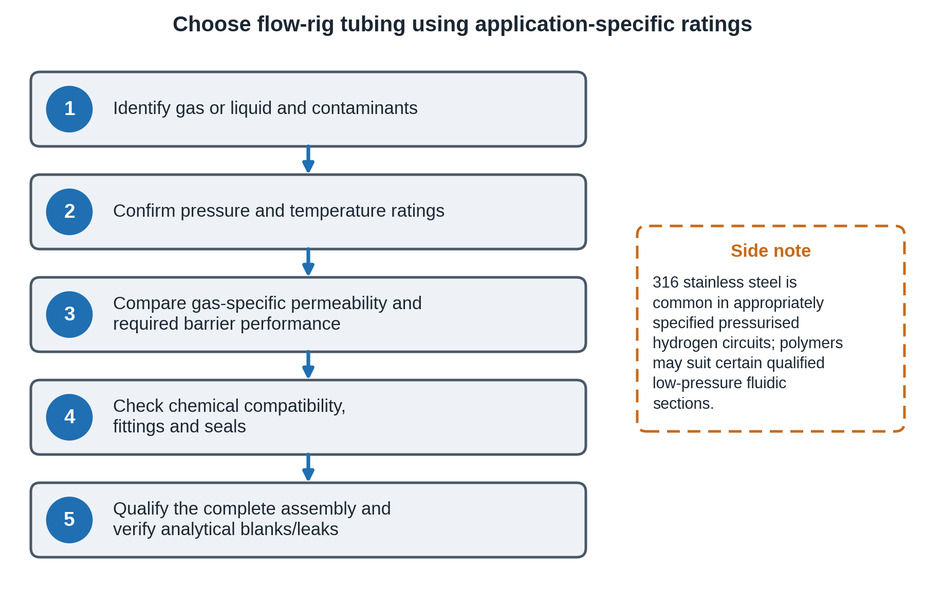
Gas can diffuse through polymer tubing; the rate depends on the gas, exact polymer grade, temperature, pressure difference, wall thickness and line length. A peer-reviewed flow-chemistry study measured oxygen ingress through PFA and showed lower ingress through ETFE under the tested conditions. Neither comparison establishes a universal permeability ranking for hydrogen, oxygen and CO₂. For critical work, compare gas-specific data for the actual tubing grade and verify chemical, pressure and temperature ratings.
A word of caution on hydrogen specifically. Polymer permeability rankings vary with the measured gas, material grade and test conditions; they must not be used as a substitute for gas-service pressure, temperature and fitting approval. For pressurised hydrogen or oxygen service, specify tubing and fittings that are approved for the gas, pressure and operating temperature; appropriately specified 316 stainless-steel tubing is commonly used in laboratory hydrogen systems. Polymer tubing may be appropriate in selected low-pressure analytical sections, but only where the exact product and assembly are rated and gas loss is acceptable. Minimise line length where permeation affects composition.
Why it matters at the bench
Three effects are common.
- Oxygen ingress into a deaerated liquid. A gas-permeable line between a deoxygenated reservoir and the cell may allow oxygen ingress if the external oxygen partial pressure is higher. The resulting change may affect a potential measurement or introduce an oxygen-related reduction signal, depending on the experiment.
- Hydrogen or CO2 loss through the wall. At low flow rates, gas permeation can affect delivered gas composition or collected product amounts if a significant partial-pressure gradient exists. The size and direction of the error depend on material, wall thickness, length, temperature, pressure and gas composition; quantify or test the effect before assigning a Faradaic-efficiency error to the tubing.
- Water vapour exchange. A permeable gas line can exchange water vapour with its surroundings; actual dew point at the cell may differ from the humidifier setting, especially if the gas encounters cooling or pressure changes.
Chemical compatibility
KOH and NaOH electrolytes at 1 M to 6 M attack some elastomers and glass, and strong acids such as 0.5 M H₂SO₄ attack others. Plasticised polyvinyl chloride tubing can release plasticiser into the liquid, which is a contamination risk for catalyst-sensitive measurements.
Practical selection guide
| Line | Typical fluid | Preferred material | Avoid | Bench tip |
|---|---|---|---|---|
| Hydrogen, oxygen, CO2 feed | Dry or humidified gas | Gas-rated metal or polymer tubing; verify exact gas, pressure, temperature and fitting ratings | Unrated assemblies; excessive permeation or incompatible fittings | Minimise dead volume and verify seals, pressure rating and gas-specific losses |
| Heated humidified gas | Water vapour in gas | Manufacturer-rated heated gas line with suitable tubing, temperature control and insulation | Materials or fittings not rated for maximum temperature and pressure | Fit a thermocouple under the insulation, not on the surface |
| Alkaline electrolyte | 0.1 M to 6 M KOH | Compatible fluoropolymer, polypropylene or PEEK grade, subject to chemical and thermal rating | Plasticised PVC and glass at high concentration | Check the pump tube material separately from the line |
| Acidic electrolyte | 0.05 M to 1 M H₂SO₄ | Fluoropolymer or PEEK | Soft elastomers without a resistance chart | Blank test before first use |
| CO2-saturated catholyte | Bicarbonate solutions | Fluoropolymer | Unqualified permeable tubing where CO₂ exchange would bias measurements | Minimise the dead volume between saturator and cell |
| Peristaltic pump section | Compatible test liquid | A dedicated pump tube rated for the fluid | Using line tubing as pump tubing | Replace on a schedule; wall fatigue changes the flow |
Inner diameter and dead volume
For small cells, internal volume matters as much as material. A 1 m length of tubing with a 3 mm inner diameter holds about 7 mL; with a 1 mm inner diameter it holds under 1 mL. If the catholyte volume in a 5 cm² cell is a few millilitres, the line can dominate the response time of any experiment that changes concentration or gas composition. Match the inner diameter to the port and the flow rate, and keep the lines no longer than the layout requires.
Fittings
Compression fittings and ferrules need the same material discipline as the tubing. A fluoropolymer tube clamped into a metal fitting that corrodes in KOH or in chloride-containing electrolyte puts metal ions in the stream. Select tubing fittings using the actual wetted-fluid compatibility, operating temperature and pressure, sealing design and contamination requirements. Compatible polymer and corrosion-resistant metal fittings can both be suitable for liquid lines; unqualified wetted metals can introduce dissolved contaminants.
For complete test systems where the tubing, pumps and cell hardware have already been matched, the electrolyser test stations and fuel cell test stations pages describe the integrated options. For the connection of small cells and microfluidic formats, see the microfluidic accessories category.
3. Pumps: flow, pulsation and what the cell actually sees
The problem
You set the pump to 10 mL/min and the display agrees. Whether the cell receives 10 mL/min as a smooth stream is another matter.
Peristaltic pumps are a common option for electrolyte recirculation. The fluid contacts only the pump tube, there is no seal to corrode, and the pump tolerates modest bubbles. Their weaknesses are pulsation, tube fatigue, and the fact that the pump tube is a consumable whose wall properties change with time. Pump-tube wear, compression set and changes in back-pressure can alter the delivered flow at a fixed speed, so periodic verification and recalibration are important during extended operation.
Pulsation produces a periodic pressure ripple. In a flow cell with a thin channel and a gas-diffusion electrode, the ripple can push electrolyte through the porous layer in pulses, which appears as periodic noise in the current at constant potential. Two fixes are practical: where needed, fit a manufacturer-rated pulsation dampener compatible with the electrolyte, pressure and gas hazards; and verify the flow and pressure fluctuation at the cell inlet under representative operating conditions.
Syringe pumps deliver very low flows with minimal pulsation, which suits microfluidic cells and small-volume experiments. The limitation is capacity: a syringe empties, so long runs need two syringes with valves or a different pump. For extended experiments, consider syringe capacity, refill interruptions, pressure capability and any required changeover system.
Diaphragm and gear pumps reach higher flow rates and pressures for larger cells and stacks. Check the wetted materials against your electrolyte, and check allowable particle size, viscosity, seal materials and required pressure range for the specific gear-pump design.
Choosing the flow rate
For a liquid-fed electrolyser, the flow needs to be high enough to remove bubbles and heat and keep concentration gradients small, and low enough to avoid excessive pressure and parasitic pumping losses. The Membranes study mentioned above is the reminder that flow is a variable: report it, hold it constant between runs, and test two or three values as part of the method development. Choose a starting flow from the cell geometry, expected gas evolution, reactant supply, heat removal and pressure limits, then test the influence of flow on the measured response.
Pump flow calibration
Collect the outlet into a tared vessel for a measured interval Δt under conditions that represent the operating circuit. Weigh the collected liquid (mass m) and calculate Q = m/(ρ × Δt), where ρ is the electrolyte density at the relevant temperature. For example, divide the measured volume by five minutes to report mL/min for a five-minute collection. Repeat after changing pump tubing and whenever back-pressure or fluid properties change; record the actual flow with the electrochemical data.
Priming and bubbles
Prime the pump and lines using the manufacturer-approved bypass or priming procedure, where available, to limit gas slugs entering the flow field. Where the cell and flow-field manufacturer permit it, orient and route the liquid inlets/outlets to promote bubble removal; do not reverse a specified port assignment solely to achieve bottom-to-top flow. Where possible, place an inline bubble trap before the cell inlet.
Gas-phase counterparts
For gas feeds, the equivalent of the pump is the mass flow controller and the regulator, covered in section 5. For CO₂-saturated catholyte, control the liquid feed and gas–liquid equilibration independently where practical. If the circuit must transport two-phase flow, select a pump and separator arrangement specifically designed for that duty.
For configurations that combine cells, pumps and controls within a specified test station, the balance of plant test station and system integration pages show how those pieces are integrated. For standalone pumping needs, the pumps and fluid handling category is the place to look, and the technical team can advise on matching a pump to your cell and electrolyte before you order.
4. Reservoirs and electrolyte conditioning
The problem
The electrolyte you prepared on Monday is not the electrolyte in the cell on Friday. It has absorbed CO2 from the headspace, warmed and cooled with the room, lost water to evaporation, and possibly picked up contaminants from the container walls.
Material
For alkaline electrolytes, select vessels such as appropriately rated polypropylene, polyethylene or fluoropolymers after checking concentration, operating temperature and contamination requirements. Borosilicate glass is slowly etched by hot concentrated KOH and releases silicate into solution, which can deposit on electrodes and membranes over long runs. For compatible aqueous acids and neutral electrolytes, borosilicate glass may be suitable after checking chemical compatibility, temperature and contamination requirements. For trace-metal-sensitive work, use a validated cleaning and blank protocol compatible with the vessel material and the required detection limits.
Volume
The reservoir volume sets how fast the electrolyte composition drifts. In a recirculating loop, products and concentration changes accumulate in the reservoir. A larger volume slows drift but slows heating and response as well. Choose the reservoir volume using expected product accumulation, concentration drift, temperature-control response, pump priming and sampling requirements; report the actual working volume and refresh interval.
Carbon dioxide and alkaline electrolyte
Open or poorly sealed KOH reservoirs absorb CO₂ from air; the resulting reactions consume hydroxide and form carbonate and/or bicarbonate, changing electrolyte speciation, effective alkalinity, pH and anion transport in an anion-exchange membrane. Do not assume that total ionic strength necessarily decreases. For anion exchange membrane work, where the membrane and ionomer are sensitive to carbonate, this matters. Limit atmospheric CO₂ exposure using a suitable covered reservoir, inert headspace or CO₂-control arrangement. Any vessel that can evolve gas or develop pressure requires a compatible, site-approved vent/relief route; record electrolyte preparation and renewal intervals.
Degassing and purging
For experiments that need deaerated electrolyte, sparge with a suitable inert gas until the required dissolved-oxygen target is achieved for that reservoir, liquid volume and flow arrangement, and maintain appropriate headspace protection during the run. A sparge line that stays submerged during operation generates bubbles that can enter the pump; use a headspace purge once the electrolyte is deaerated.
Return line and headspace
Arrange the liquid return to minimise splashing, gas entrainment and unwanted pressure losses, in accordance with the actual separator and reservoir design. Where hydrogen can evolve or enter the reservoir headspace, route the gas through an engineered, approved hydrogen exhaust arrangement (see section 8).
Temperature
If the experiment is run above room temperature, put the heater in the reservoir or on the line, with the temperature sensor in the liquid and not on the outside wall. Insulate the lines between the reservoir and the cell.
Separate anolyte and catholyte loops
Where the cell has two liquid compartments, use two reservoirs and two pumps unless the experiment specifically requires a shared loop. Shared reservoirs can mix soluble products; in some CO₂-reduction arrangements, cathode products can cross into anode-side liquid and be oxidised. Never combine circuits if the configuration could mix incompatible hydrogen-bearing and oxygen-bearing streams. Control and, where possible, measure pressures at both cell compartments so that the differential pressure stays within the membrane/cell supplier’s limit. Similar line lengths or nominal pump flow rates do not by themselves guarantee hydraulic balance.
Level and volume tracking
Mark the fill level on the reservoir, note the starting volume, and measure it again at the end of the run. Changes in reservoir volume may reflect sampling, evaporation, leakage, electro-osmotic transport or reaction water balance; investigate deviations against the experiment-specific mass balance and measurement uncertainty.
For flow batteries and CO2 reduction configurations, the redox flow battery test station and CO2 reduction test station pages describe configurations in which the reservoirs, pumps and cells are specified together. For the membranes that separate the two loops, see the ion-exchange membranes category.
5. Gas routing: flow control, stoichiometry and purge logic
The problem
The gas arrives at the cell at a flow rate, composition and pressure that you chose, or it does not, and the data cannot tell you which.
Flow control
Mass flow controllers are calibrated for a specific gas and reference condition. Confirm the gas, range and reference temperature on each controller, and operate within the actual model’s specified accurate measurement and control range; there is no universal 10–100% limit. A 5 L/min controller may be unsuitable for a 20 mL/min feed unless its specified turndown, accuracy and stability support that flow.
Working out the flow you need
For a hydrogen–air PEM fuel cell, the molar hydrogen consumption rate is I/(2F), which comes to about 6.97 mL/min of hydrogen per ampere at 0 °C and 1 atm. Oxygen consumption is half the molar rate of hydrogen, and since air contains about 21% oxygen, the stoichiometric air flow is about 16.7 mL/min per ampere. Multiply by the stoichiometric ratio you want.
For a 25 cm² cell at 1 A/cm², the current is 25 A. At a hydrogen stoichiometry of 1.5, the hydrogen flow is about 261 mL/min. At an air stoichiometry of 2.0, the air flow is about 835 mL/min. At low current density the calculated flow can fall below the minimum useful range of the controller, and a fixed minimum flow is used instead. Report which one you used, because the stoichiometry at low current is then much higher than the nominal value.
Flow direction
The European Commission JRC harmonised automotive PEM fuel-cell single-cell protocol specifies counter-flow for comparative assessment within that protocol. Other applications may use co-flow, counter-flow or other arrangements. State the direction in your methods, and apply the exact JRC operating conditions only when claiming comparability with that protocol.
Pressure and back-pressure
For pressurised experiments, use the pressure-control, back-pressure, relief and differential-pressure arrangements approved for the cell and station. Where an outlet back-pressure regulator is used, verify its gas compatibility and ratings, and control the pressure on both sides so the permitted membrane differential is never exceeded. A rapid pressure change on one side can damage a thin membrane.
Purge logic
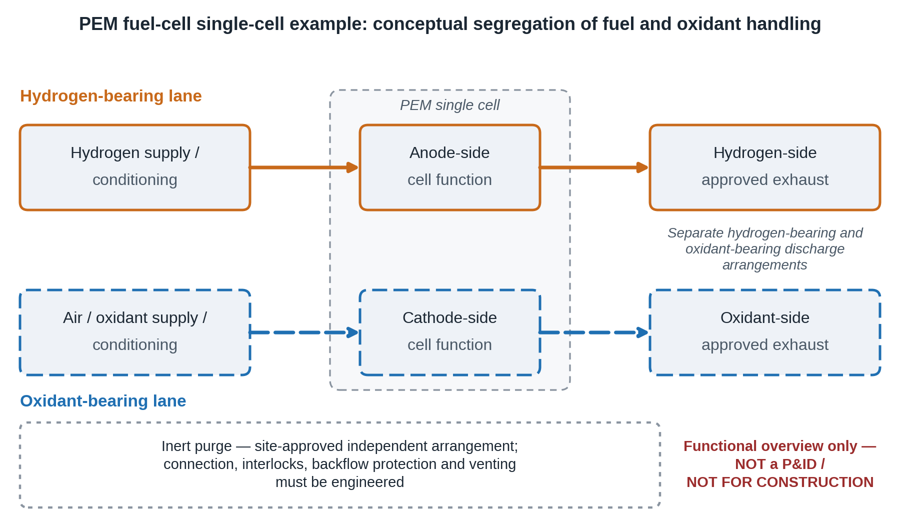
Hydrogen-bearing gas circuits require a documented inert-gas purge arrangement, selected for the cell design, gas lines and approved exhaust. Where both electrodes have gas lines, hydrogen and oxidant systems must remain segregated with safeguards against cross-connection and backflow. The sequence matters. Before hydrogen service and before maintenance, verify that purging and isolation meet the site-approved acceptance criteria; route purge gases through the approved exhaust and prevent inert-gas backflow or cross-contamination. Membrane hydration during storage and shutdown must follow the cell manufacturer’s procedure rather than a universal dry-purge instruction.
Check valves and isolation
Select backflow prevention and isolation for each gas circuit from the pressure, condensate and failure scenarios; check valves alone may not prevent all reverse flow or cross-contamination, and moisture protection may require additional components. Provide the isolation, pressure instrumentation, backflow safeguards and relief paths specified in the approved circuit design; leak testing must use the manufacturer’s procedure, not ad hoc closure of vents.
Outlet management
The anode and cathode outlets should not be allowed to share a vent line where hydrogen and oxygen could mix. Route hydrogen-bearing and oxygen-bearing outlets, purges and relief discharges through separately assessed, compatible exhaust arrangements to approved discharge locations. Traps and bubblers must not cause blockage, liquid carry-over or excessive back-pressure, and an ordinary fume cupboard is not automatically an approved hydrogen exhaust system. Ventilation, dilution, drainage, pressure relief and isolation must be confirmed in the site safety design. Where CO₂-reduction products are analysed by gas chromatography, include a compatible sampling arrangement and account for any gases or soluble products retained in condensate or traps when calculating product balances.
Gas quality
Specify gas purity, trace contaminants and conditioning according to the measurement and instrument requirements. Verify cylinder certificates and supply-line integrity where relevant; use filters, dryers or oxygen-removal devices only where compatible with the intended gas stream, safety design and humidity target.
For integrated flow control, humidification and exhaust handling designed around a single cell or small stack, the PEMFC test station pages are the relevant starting point. For water electrolysis, see the PEMWE, AEMWE, and alkaline electrolyser categories.
6. Humidification and condensation control
The problem
In a PEM fuel cell, water supports proton conduction through the membrane, while excessive liquid water can restrict gas access. Anion-exchange membrane systems conduct anions and have different water-management requirements. The appropriate water balance depends on the membrane, cell design and operating mode; the humidifier, gas lines, temperature and pressure controls can all influence it.
Why humidify at all
In a PEM fuel cell, dry reactant gas can remove water and reduce membrane hydration, although self-humidified designs and operating regimes may not require external humidification. Where humidification is used, select and report the inlet gas humidity, cell temperature and pressure because membrane water content affects proton conductivity and cell resistance.
Dew point is the control variable
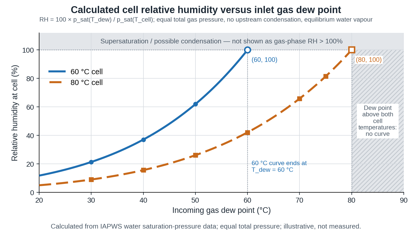
Relative humidity depends on both the water content and the temperature, so the same gas stream has different relative humidity at different temperatures. Control the dew point at the humidifier, and then calculate the relative humidity at the cell temperature. At approximately unchanged total pressure and with no upstream condensation, a 70 °C inlet dew point corresponds to about 66% relative humidity at an 80 °C cell, based on the ratio of saturated water-vapour pressures. Pressure changes and cold fittings alter the delivered water-vapour partial pressure. If the delivered vapour pressure exceeds saturation at the local temperature, condensation may occur in the line or cell.
Humidifier types
Three arrangements are common on test benches.
- Bubbler (sparger) humidifiers pass the gas through a heated water column. They are simple and robust, but the delivered dew point lags the water temperature, depends on flow rate and water level, and can fall short of saturation at high flows.
- Membrane humidifiers exchange water vapour across a membrane from heated water to the gas. They are compact and give smooth output, but the exchange capacity is limited at high flow.
- Injection (direct liquid metering) humidifiers meter liquid water into the gas stream and evaporate it.
Some cell designs manage membrane hydration using internal water transport or in-cell humidification. Whether an external humidifier or heated feed line is needed depends on the operating mode, pressure, cell design and validated conditioning procedure.
Heated lines
Everything between the humidifier and the cell should be warmer than the dew point, otherwise water condenses in the line and arrives as slugs. Published test-station work reports that the gas temperature must be kept above the dew point temperature by a margin to avoid condensation. A margin of several degrees may be useful, but the required margin depends on measurement uncertainty, insulation, operating pressure and cold spots. Use an appropriately rated heated gas line and independent temperature control/over-temperature protection, including attention to cell inlet fittings.
Signs of condensation
Pressure or flow oscillations, changing voltage and altered low-frequency impedance may be consistent with intermittent condensation or flooding, but none is diagnostic on its own. Check line and fitting temperatures, traps, humidity settings and other potential causes before attributing the response to water.
Start-up and shutdown order
Follow the cell and humidifier manufacturers’ conditioning procedures and the site-approved gas-handling sequence. Coordinate cell, line and humidifier temperatures to minimise condensation without dehydrating a membrane that requires hydration. A dry-gas warm-up or a fixed heater shutdown order must not be presented as suitable for every PEMFC, electrolyser or MEA configuration.
Liquid-fed and CO2 systems
In liquid-fed electrolysers, gas outlets can carry substantial water vapour and entrained droplets; exhaust condensation, liquid separation and drainage must be handled by the approved gas-management system. In gas-fed CO₂ electrolysis, the need for feed humidification and the risk of carbonate/bicarbonate salt deposition depend on membrane type, cation transport, local concentration and water balance, including wetting and drying of the gas-diffusion electrode.
For humidified test configurations built around a controlled cell, see the fuel cell test stations and module control and measurement pages.
7. Leak checks and a commissioning sequence
The problem
Leaks can release reactants, admit air into sub-ambient-pressure sections and cause both measurement errors and safety hazards. The direction and severity of gas exchange depend on the pressure differences and circuit design. Some defects become apparent only at particular operating pressures or temperatures, while membrane permeation and internal sealing faults can occur without an external leak.
Define the acceptance threshold first
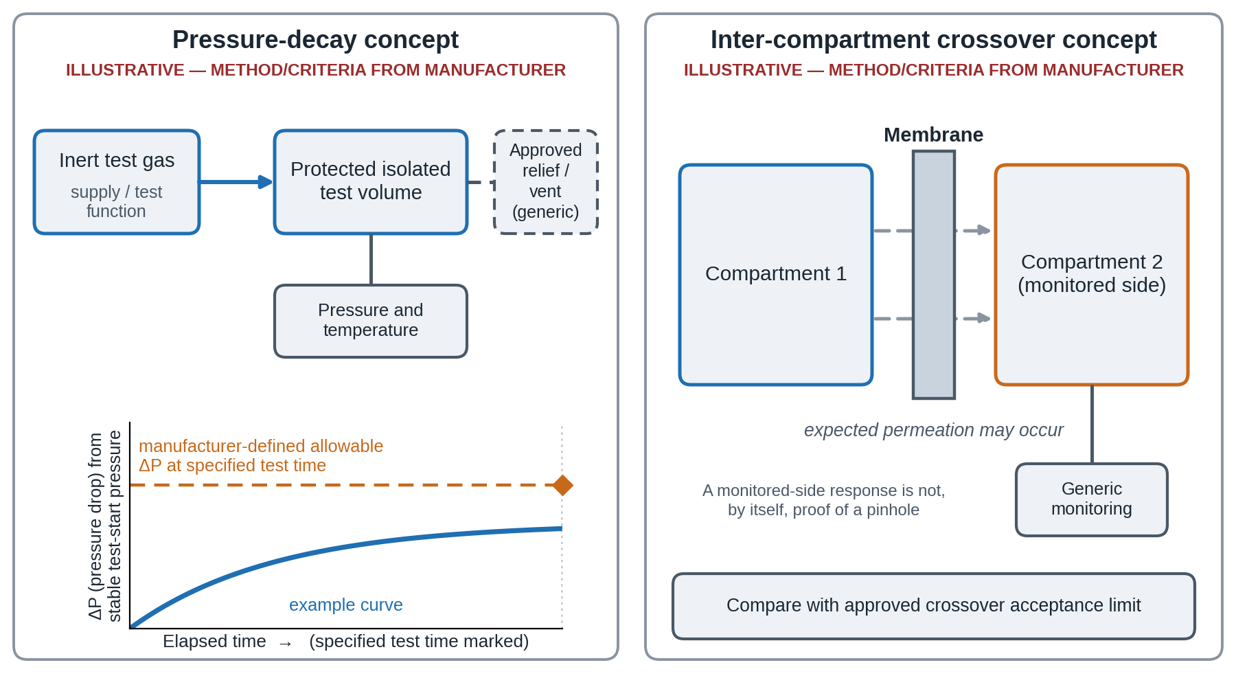
Write down before starting what counts as a pass. Use a pass/fail criterion validated for the specific circuit and application, considering test gas, isolated volume, pressure, temperature stability, test time, sensor uncertainty and the permitted leak rate; no single pressure-drop number is suitable for all rigs. Pressure-decay sensitivity also depends on gas compressibility, effective test volume, temperature change and the location of any leak. Record the volume, pressure, duration and result in the experiment log.
Step-by-step commissioning
- Visual and mechanical check. Verify component identity, cleanliness, connection seating and the manufacturer’s specified assembly method and tightening limits. Follow the cell supplier’s approved clamping pattern, torque settings and permitted operating state; do not apply an invented universal fitting turn or compression method.
- Dry run with water or neutral electrolyte. Where compatible with the wetted materials and required cleanliness, perform a liquid-loop integrity check using the approved test fluid and manufacturer-specified duration/pressure. Use appropriate secondary containment and inspect the accessible fittings before introducing hazardous electrolyte.
- Gas pressure-decay test. Under an approved commissioning procedure, isolate each gas circuit and test with a suitable inert gas, keeping the test pressure below every component limit and retaining the required overpressure protection and safe depressurisation route. Allow temperature to stabilise, then record pressure, temperature, circuit volume, duration and the pre-defined acceptance criterion. Use a pressure instrument with appropriate accuracy and resolution for the criterion; repeat on the second circuit as required.
- Cross-leak test. Where inter-compartment leakage assessment is required, follow the manufacturer’s validated procedure, including permitted differential pressure, suitable test gas, pressure protection, monitored-side configuration and expected background permeation. A monitored-side response may reflect normal membrane gas permeation or an internal sealing defect. Interpret it against the supplier’s approved crossover test, permitted pressure difference and a defined baseline/acceptance limit. Keep the differential within the membrane limits.
- Hydrogen detection. After the rig has passed its approved inert-gas tests and the responsible operator authorises gas introduction, use the fixed or portable hydrogen detection methods specified in the laboratory safety procedure. A handheld detector is supplementary and must not replace engineered interlocks or prior leak checks.
- Electrolyte leak detection. For caustic electrolytes, inspect for leakage using methods approved for the chemicals and equipment. If a leak is detected, isolate the system safely and follow the laboratory spill-response procedure with the required personal protective equipment; do not touch leaking or pressurised joints.
- Hot re-check. Monitor for leaks and pressure/flow changes after thermal equilibration using the station’s approved hot-operation checks. Do not reapply a cold pressure-decay/crossover procedure or adjust fasteners on hot or pressurised equipment unless the manufacturer explicitly provides a safe method.
- Record a baseline. Record the applicable baseline values for the cell and operating mode—for example, open-circuit voltage for a fuel cell where relevant, high-frequency resistance when a valid impedance measurement is available, and measured gas/liquid flows and temperatures. Use the same measurement conditions for subsequent comparisons.
When the cell passes but the data still drift
Recheck the pump tube, the humidifier water level, the nitrogen purge line for trace oxygen, and the reservoir for carbonate. These are the usual suspects when the pressure test is clean.
For in-situ and operando configurations, where the window or port adds more sealing surfaces, see the in-situ and operando electrochemical cells category.
8. Safety: hydrogen, caustic electrolyte and pressure
The problem
A flow rig combines flammable gas, caustic liquid, electrical power, heat and sometimes pressure on a laboratory bench. Each is manageable alone. Together they need a deliberate plan, written before the first run.
Hydrogen
Hydrogen is flammable across a very wide range, from about 4% to 75% by volume in air, and needs very little energy to ignite. The safety strategy is simple to state: keep the inventory small, keep it contained, and keep it ventilated.
- Use site-approved ventilation and hydrogen detection designed for the assessed release scenarios, enclosure geometry and airflow. Sensor positioning, alarm thresholds and safe discharge locations require specialist review; a generic fume cupboard or a single high-mounted detector does not by itself establish adequate hydrogen safety.
- Locate and secure cylinders, regulators, isolation devices and flow-limiting protection according to the approved compressed-gas installation and local requirements.
- Assess ignition, reverse-flow and flame-propagation scenarios for the actual gas circuit, and use only protection devices appropriate to the service and approved design; flame/flashback arrestors are not universally needed for all hydrogen lines and may introduce flow restriction.
- Lead each vent to a safe place, never into the room, and never join anode and cathode vents.
- Use the approved inert-gas purge and gas-clearance procedure before introducing hydrogen and before maintenance, as applicable to the system (section 5).
- Remove ignition sources, and check that all electrical equipment near the cell is rated and earthed appropriately.
Crossover and accumulation
Define gas-crossover monitoring, alarm limits and protective shutdown actions from the cell/test-station safety assessment, including low-current and high-pressure operation where relevant. A chosen current or voltage floor is not a substitute for validated crossover limits, gas-purity detection or safety interlocks.
Caustic and acidic electrolyte
1 M to 6 M KOH causes serious eye damage and skin burns. Wear splash-resistant eye protection and chemical-resistant gloves, keep a labelled spill kit and an eyewash within reach, and use secondary containment, such as a tray, under the reservoir and pump. Use a closed transfer method for filling, and never run an uncontained caustic line across a walkway. For acidic electrolytes, follow the chemical safety data sheet and institutional personal-protection and spill-response procedures; do not improvise spill neutralisation.
Pressure
Pressurised sections require a documented design that provides appropriate pressure regulation, instrumentation, overpressure protection and relief discharge routes. Relief-device selection, set pressure and capacity must protect every relevant component under the assessed fault cases, including back-pressure; never exceed the cell’s specified operating or differential-pressure limits. Depressurisation must follow the approved procedure. Tubing and fittings degrade with temperature and chemical exposure, so inspect and replace on a schedule.
Electrical
Isolate the load or power supply before opening any cell connection. Use electrical isolation, overcurrent protection, operating limits and independent protective functions appropriate to the installed power supply/load and station risk assessment; follow the manufacturer’s rated voltage, current and emergency-stop provisions.
Heated lines and surfaces
Heating tape on humidified lines can reach temperatures that cause burns and can soften plastic tubing. Use temperature controllers with an over-temperature cut-out, label hot surfaces, and insulate.
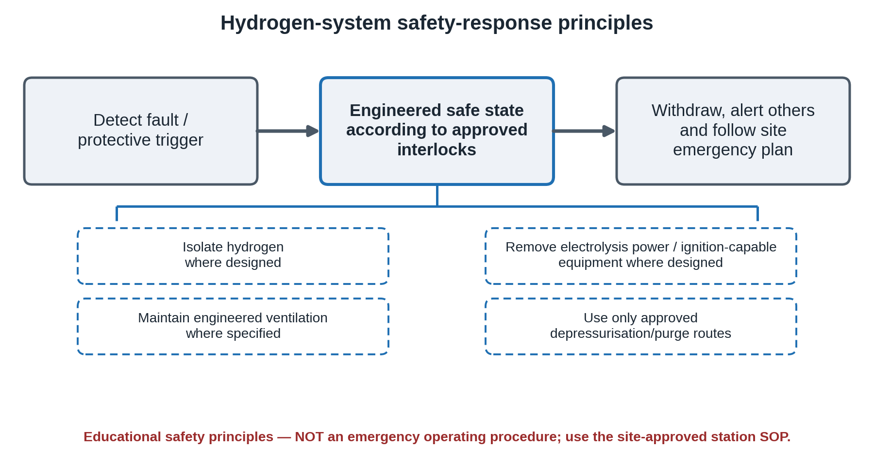
Emergency response must follow a written, site-approved procedure developed for the actual test station, hazards and controls. Hydrogen detection, loss of ventilation, excessive pressure, crossover or fire may require automatic isolation of hydrogen, removal of electrolysis power and ignition-capable equipment, and continued operation of the engineered ventilation system. Depressurisation or inert-gas purging must occur only through validated, safe routes when the system permits. Operators should withdraw and follow site emergency instructions rather than approach a suspected hydrogen leak. Train and rehearse the approved procedure before operating the rig.
Risk assessment and training
This guide gives bench practice and is not a substitute for your institution’s risk assessment, local regulations or the relevant Australian and New Zealand standards for compressed gases and hydrogen. Do the assessment before the first experiment, update it when the configuration changes, and keep a record.
9. Master decision matrix
Use the matrix to move from the experiment you are running to a sensible starting arrangement. The category column links to ScienceGears product groups rather than verifying a particular model, pressure rating or operating configuration. Check the specification of any item against your cell and electrolyte before ordering.
| Application | Recommended arrangement | Relevant ScienceGears category | Key rationale | Key constraint |
|---|---|---|---|---|
| PEM fuel cell single-cell testing | Protocol-matched flow arrangement, temperature/humidity control and gas flow metering | PEMFC test station | Match the selected PEMFC protocol where formal comparison is intended | Manage dew point and cell pressure to meet specified RH without unintended condensation |
| PEM water electrolysis, small cell | Recirculating deionised water, PTFE or PEEK lines | PEMWE test station | Bubble removal and temperature control | Water conductivity must stay low |
| AEM water electrolysis | Manufacturer-specified water or dilute-alkali feed; compatible reservoir and tubing | AEMWE test station | Flow rate affects kinetics and cell resistance | Carbonation, water purity and membrane/ionomer compatibility depend on feed choice |
| Alkaline water electrolysis | Compatible alkaline electrolyte circulation with engineered gas–liquid separation | Alkaline electrolyser test station | Component compatibility must cover KOH concentration and operating temperature | Avoid glass at high concentration |
| CO2 reduction in an MEA cell | Control CO₂ feed and water balance; provide independent liquid loops only where the cell has both | CO2 reduction test station | Limits avoidable product mixing and supports gas/liquid product accounting | Salt deposition depends on local concentration, water transport, temperature and drying conditions |
| Redox flow battery cell | Two electrolyte reservoirs and pumps, with cell pressure monitoring/control | Redox flow battery test station | Pressure monitoring helps limit unwanted membrane differential | Pump tube compatibility with the redox couple |
| Small-volume or microfluidic flow cell | Syringe pump, short low-volume tubing | Microfluidic accessories | Smooth flow at very low rates | Syringe capacity limits run length |
| Spectroelectrochemical or operando cell | Pulsation-damped pump, bubble trap before inlet | In-situ and operando cells | Bubbles and pulses disturb optical signals | Window and port seals add leak paths |
| Membrane characterisation in flow | Matched membrane and cell, controlled temperature | Ion-exchange membranes | Membrane pretreatment sets baseline resistance | Pressure differential limit |
| Gas-fed MEA with porous current collector | Gas flow metering and pressure regulation where specified by the cell design | Metal foam electrodes | Porous layers need steady, controlled flow | Material choice, contact resistance and compression uniformity |
| Complete bench with balance of plant | Integrated pumps, gas panel, heaters and controls | Balance of plant test station | Components specified together | Footprint and ventilation |
| Custom or mixed configuration | Specified with the technical team | System integration | Avoids mismatched parts | Lead time depends on the design |
10. Frequently asked questions
What is the best tubing material for hydrogen and oxygen lines on an MEA test rig?
Choose tubing by gas-service approval, pressure, temperature, permeability and fitting compatibility rather than polymer name alone; appropriately specified 316 stainless-steel tubing is a common option for pressurised hydrogen circuits, while suitable polymers may be used in qualified low-pressure fluidic sections. Silicone can exhibit substantial gas permeation compared with selected other tubing polymers, but permeability rankings vary with the gas, polymer grade and conditions. Minimise dead volume and line length where relevant, and verify the actual assembly ratings and allowable gas losses.
Should I use a peristaltic pump or a syringe pump for electrolyte circulation?
Use a peristaltic pump for continuous recirculation over hours or days, because it does not run out and the fluid touches only the pump tube. Use a syringe pump for very low flows, short experiments and microfluidic cells, where smooth delivery matters more than run length. Whichever you choose, calibrate the delivered flow by weighing the outlet.
How do I stop condensation in humidified gas lines?
Control the dew point at the humidifier, and keep every section of line between the humidifier and the cell warmer than that dew point. Put the temperature sensor under the insulation, heat and insulate the cell inlet fitting, and keep the dew point at or below the cell temperature as specified for the required humidity and operating pressure, while preventing unintended condensation.
How do I leak-test a flow cell before running hydrogen?
Follow the specific cell and site-approved commissioning procedure. This may include a compatible liquid-loop check, a protected inert-gas leak test and a separate inter-compartment crossover assessment, each with documented limits for pressure, temperature and leakage. Introduce hydrogen only after the required equipment, ventilation and safety-interlock checks have passed and the responsible operator has authorised startup.
Why does my KOH electrolyte change performance over a few days?
Open or poorly sealed reservoirs absorb carbon dioxide from the air, consuming hydroxide and introducing carbonate/bicarbonate, which changes solution chemistry and can alter pH, transport properties and performance; ionic strength does not necessarily decrease. Evaporation also changes the concentration. Limit exposure to atmospheric CO₂ using a compatible headspace/CO₂-control arrangement with safe venting where gas or pressure can develop; track electrolyte volume and prepare or replace it according to a documented procedure.
What flow rate should I use for my reactant gases?
For a hydrogen–air PEM fuel-cell test, calculate reactant consumption from cell current. Hydrogen consumption is about 6.97 mL/min per ampere at 0 °C and 1 atm, and air is about 16.7 mL/min per ampere for complete oxygen use, both multiplied by the stoichiometric ratio you choose. At low current the calculated value may fall below the mass flow controller’s useful range, so state the minimum flow you actually used.
11. Expert support: how ScienceGears works alongside your research
ScienceGears provides technical guidance on electrochemical flow-cell and MEA test accessories, including chemical compatibility, controlled operating conditions and troubleshooting. Our approach is to help researchers specify components that suit their intended cell configuration and measurement requirements.
Pre-purchase configuration check
Before you order, tell us your cell, electrolyte, temperature, flow range and gases, and the technical team will go through the tubing, pump, reservoir and gas-routing arrangement with you, flagging compatibility issues before they cost you time. Talk to our technical team →
Leak and condensation diagnosis
If a rig you already own gives drifting resistance, noisy current or inconsistent repeats, send us the configuration and the symptoms. We will work through the likely causes with you: pump tube wear, line temperature, dew-point margin, carbonate uptake or a slow leak.
Complete system supply
- MEA test cells
- Electrolyser test stations
- Fuel cell test stations
- Balance of plant test station
- Pumps and fluid handling
- Microfluidic accessories
- Ion-exchange membranes
- Other electrochemistry accessories
Stock availability and delivery
We support customers in Australia and New Zealand. Stock availability, dispatch timing and delivery estimates are confirmed for the requested items at the quotation or order stage; custom-built systems may require additional lead time.
“A good flow rig is one where the cell is the only thing you have to wonder about.”
12. Further reading
Related ScienceGears blog posts
Product pages
- Electrochemical cell
- MEA test cells
- PEMWE test station
- AEMWE test station
- Alkaline electrolyser test station
- PEMFC test station
- CO2 reduction test station
- Redox flow battery test station
- Module control and measurement
- System integration
- Metal foam electrodes
- In-situ and operando electrochemical cells
13. Get in touch
Tell us what you are building, and we will help you specify the cell, pumps, tubing, reservoirs and gas handling so that they work together from the first run.