

By the end of this guide you will be able to pick a working electrode material, diameter and format for a given electrolyte and technique, predict roughly how much current and iR drop to expect before you order it, and know which surface check confirms the electrode is behaving as it should.
1. Why the working electrode decides what you can measure
When a cyclic voltammogram looks unexpected, investigate the electrode surface, cell conditions and instrument setup. The electrode material may contribute an overlapping background feature: hydrogen adsorption peaks overlapping your catalyst's onset on platinum, an oxide wave swamping an analyte oxidation on gold, or a background current on glassy carbon that buries a micromolar signal. The working electrode is the interface where the reaction of interest is monitored, but it can also undergo background processes that distort the measurement; the counter electrode supports a separate reaction to complete the circuit.
Three questions settle most selections, and it helps to answer them in this order:
- Which potentials do you need to reach, in which electrolyte? This eliminates materials whose own reactions (hydrogen evolution, oxide formation, solvent or carbon oxidation) fall inside your window.
- Does the surface chemistry help or hurt? Gold binds thiols. Platinum adsorbs hydrogen and catalyses its evolution. Carbon is comparatively indifferent. Whichever way it goes, the surface is part of the experiment.
- How big should the electrode be? Diameter sets current, iR drop, charging background and, below roughly 100 µm, the diffusion regime itself.
Everything else (insulating body, mounting, length, whether it rotates) is a format decision that follows from those three.
ScienceGears groups its stationary working electrodes on the working electrode range page, with separate pages for disc electrodes, carbon paste electrodes and microelectrodes. The sections below take each material in turn, then size, then the practical matters of preparation and electrolyte compatibility, and finish with one decision matrix. If you are also choosing the other two electrodes in the cell, the guide to selecting a counter electrode pairs naturally with this one.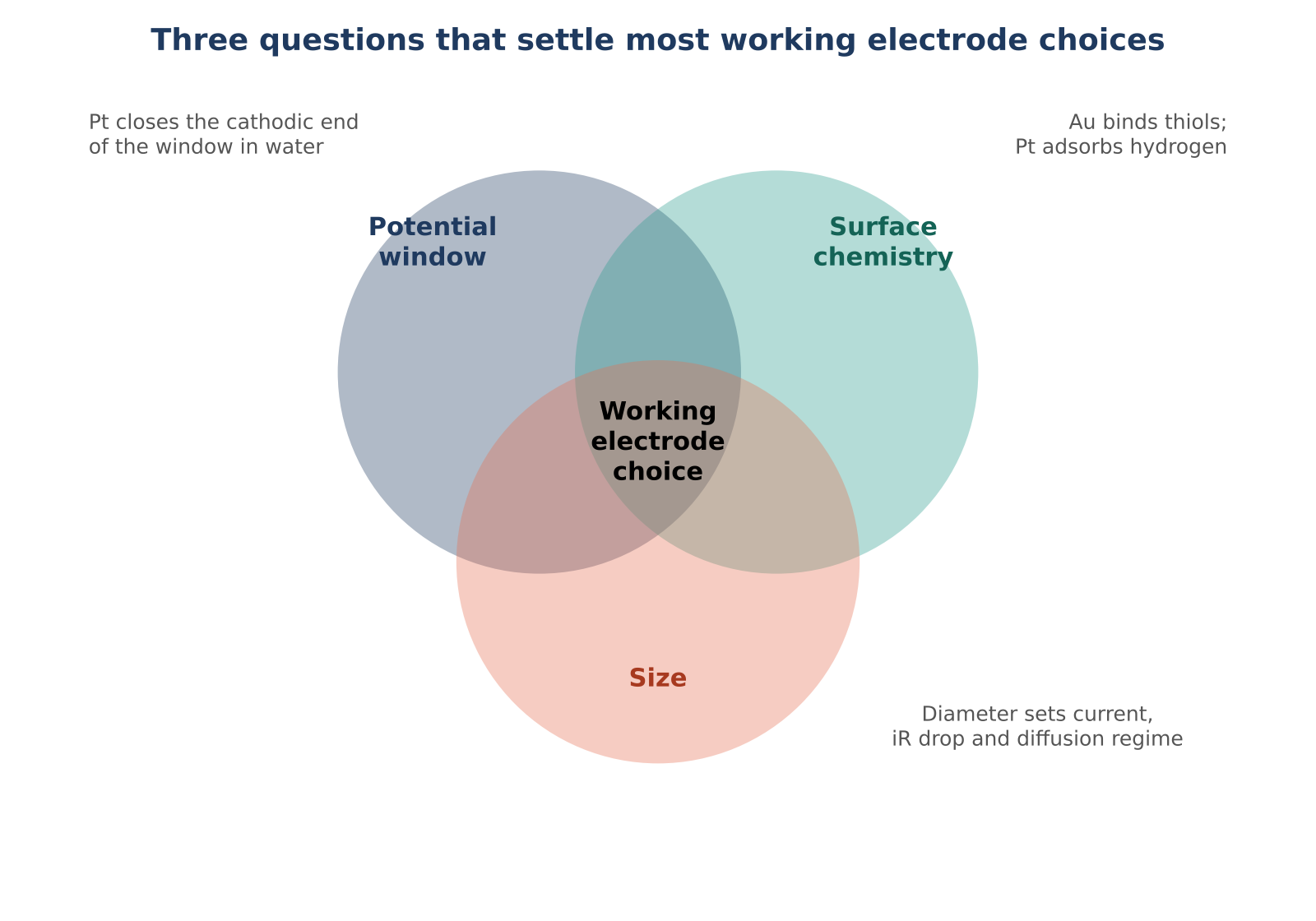
2. Start with the potential window and the electrolyte
Pick the electrode whose usable window comfortably contains the potentials your experiment needs, with some margin, before you think about anything else. The usable window is the range where current from the electrode or electrolyte themselves is negligible compared with the current from your analyte. IUPAC defines it that way, and stresses that only approximate ranges can be quoted because the limits depend on the electrode and electrolyte together.
The IUPAC reference table gives these approximate ranges, all against Ag|AgCl in 3 M KCl:
| Electrode | Medium | Approximate usable range (V vs Ag/AgCl) |
|---|---|---|
| Platinum | 1 M NaOH | −0.8 to +1.3 |
| Platinum | 1 M H₂SO₄ | 0 to +1.7 |
| Gold | 1 M H₂SO₄ | −0.4 to +1.2 |
| Carbon | 0.1 M KCl | −1.0 to +1.0 |
| Carbon | 1 M HClO₄ | 0 to +2.0 |
Read these as orientation, not as specification. The reasons behind the pattern matter more than the numbers:
- Platinum has a short cathodic window in water because it is an excellent hydrogen evolution catalyst, so hydrogen evolution starts almost as soon as the potential falls below the reversible hydrogen potential.
- Gold has a short anodic window because its surface oxidises at positive potentials, and the oxide formation and its stripping on the return scan appear as large waves in the voltammogram.
- Carbon reaches further in both directions because both hydrogen evolution and oxygen evolution are slow on it. Its anodic limit is eventually set by oxidation of the carbon surface itself.
As an initial screening step, identify the most negative and positive potentials required and allow an appropriate margin (for example, about 0.2 V where justified). Assess whether the measured background current is acceptable relative to the signal of interest; no fixed margin guarantees a suitable window. Then run a blank scan in your actual electrolyte before adding analyte. The blank tells you more about the real window than any table, because pH, buffer, trace oxygen, halides and the electrode's polishing history all shift it.
Electrolyte pH and solvent change the answer too. The same glassy carbon disc that is featureless in acid may show surface-group redox features in a different medium, and the platinum that serves well in 0.5 M H₂SO₄ gives a different hydrogen region in alkaline solution. Section 10 returns to this with a compatibility table.
For setting up the full cell around your chosen electrode, the electrochemical cell selection guide covers cell formats, and the guide to choosing reference electrodes covers the potential scale your window is quoted against.
3. Glassy carbon: the default for general voltammetry
When the chemistry of interest is a solution redox couple, a catalyst ink on a flat support, or a sensing film, glassy carbon is the sensible first choice. Its practical advantages are a broad window in both directions, low background current and good chemical stability in acid and alkali. It is not catalytically active for hydrogen or oxygen reactions to the degree metals are, which is why it is the usual support when you want to measure a catalyst rather than the electrode beneath it.
Two properties catch people out.
The surface is not inert. Glassy carbon carries oxygen-containing groups whose population depends on how it was polished and what potentials it has seen. Published work on glassy carbon as a catalyst support shows that anodic polarisation, in acid or in alkali, changes the surface and the activity of deposited platinum, and that the change persists into later measurements. The practical consequence is that a glassy carbon electrode has a history. Polish it the same way before every run, and do not carry out aggressive anodic excursions casually on an electrode you plan to reuse for kinetic comparisons.
A mirror finish matters more than it sounds. Catalyst inks are usually drop-cast onto the disc, and film uniformity depends on a flat, clean, reproducibly wetted surface. The electrode polishing kit supplies the 1.0, 0.3 and 0.05 µm alumina sequence for this, and the guide to polishing and maintaining glassy carbon, gold and platinum electrodes walks through the full routine and the CV checks that confirm it worked.
On the ScienceGears disc electrode page, glassy carbon discs are listed in diameters of 1, 2, 3, 4, 5, 6, 7, 8, 9, 10, 11.28, 12, 15 and 20 mm, with a PTFE coat. The listed construction is a brass rod of about 20 mm, a jacket of 60–100 mm and a total length of 80–120 mm. The 11.28 mm disc is worth noting: its geometric area is 1.00 cm², which makes current-to-current-density conversion trivial.
Glassy carbon also comes in other formats on the same site:
- L-type electrodes in 2, 3 and 5 mm, with a PTFE coat, a 20 mm brass rod, an 80 mm jacket and 100 mm total length. The bend helps orient the active face and position a reference probe in a constrained cell.
- Rod electrodes in 3, 4, 5 and 6 mm, 100 mm in total with an 80 mm active rod, suited to immersion and extended profiling rather than precision disc work.
- Plate electrodes, where the glassy carbon plate is 10 × 10 × 2 mm, for bulk electrolysis and higher-current work.
- A glassy carbon rotating disk electrode with a 5 mm standard disc and a PTFE or PEEK body, covered in Section 9.
Choose glassy carbon when you need a relatively broad usable potential window or a convenient support for a deposited film, provided that blank experiments confirm substrate reactions and surface oxidation do not interfere. Avoid it when the experiment depends on a specific metal surface, such as thiol self-assembly or platinum-specific adsorption.
4. Gold: when the surface chemistry is the experiment
For thiol-based self-assembled monolayers, gold is commonly selected because of its well-established sulfur–gold surface chemistry. Self-assembled monolayers, thiolated DNA or aptamer sensors and many biosensing architectures rely on the strong gold–sulfur bond, and the quality of the monolayer depends on the quality of the surface. Gold is also a common surface for adsorption studies and is widely used in CO₂ reduction work, where its behaviour as a metal differs from that of platinum.
The cost of gold is its anodic limit. In the IUPAC table above, gold's usable range in 1 M H₂SO₄ ends near +1.2 V against Ag|AgCl, and the surface oxide that forms before that is not a nuisance to be avoided but a feature to be understood. The reduction of that oxide on the return scan is also the standard way to estimate the real surface area of polycrystalline gold, a point developed in Section 7.
Three practical points follow from gold being soft and chemically specific:
- Polish lightly. Heavy pressure can embed abrasive and round the disc edge, which changes the effective area over time. The polishing guide linked in Section 3 covers pressure and pad separation, including keeping a gold-only pad set so that harder debris from other materials does not drag across the surface.
- Keep it away from potentials that over-oxidise it unless the oxide region is what you are studying. If you need to scan anodically in a chloride-containing electrolyte, check the practical limit with a blank scan rather than assuming the sulfate-based number applies.
- Do not assume the polished surface is defect-free before monolayer formation. Mechanical polishing gives a reproducible surface, not an atomically ideal one.
The disc electrode page lists gold discs at 0.5, 1, 2, 3, 4, 5 and 6 mm. Gold L-type electrodes are listed at 2, 3 and 5 mm on the L-type page, and a gold rotating disk electrode is available on the RDE and RRDE page. For small-volume or high-resistance work, gold is also offered as a gold microelectrode in 10, 25, 50, 100 and 200 µm diameters.
Choose gold for thiol chemistry, adsorption studies and sensing on gold-bound layers. Choose something else when you need to scan far anodically in acid or in chloride, or when the experiment is a bulk solution couple that glassy carbon handles with less complication.
5. Platinum: catalysis, hydrogen and electrochemical surface diagnostics
Platinum earns its place when the reaction is a platinum reaction. Hydrogen evolution and oxidation, oxygen reduction, small-molecule oxidation and fuel-cell catalyst benchmarking all use platinum as the reference surface, because its behaviour is the benchmark the field compares against. In a suitable acid electrolyte, characteristic hydrogen and oxide features can help assess the surface condition and estimate electrochemically active area by a defined method.
The same activity that makes platinum useful limits it. Hydrogen evolution begins early on platinum, which closes the cathodic end of the window in aqueous solution, and the IUPAC table shows that the practical window depends strongly on whether the medium is acidic or alkaline. When analyte reduction overlaps substantial hydrogen evolution on platinum, glassy carbon may provide a better measurement background, provided that a blank scan confirms a usable window in the actual electrolyte.
Platinum is also sensitive to adsorbing species. Sulfur-containing compounds, halides and strongly adsorbing organics can modify or block the surface, and in a voltammogram this appears as suppressed hydrogen adsorption peaks long before it shows up in a solution couple. That sensitivity is the reason the standard diagnostic is so informative: a suitably prepared polycrystalline platinum surface in deaerated acid commonly shows hydrogen adsorption/desorption features and an oxide-reduction feature; their shape and position vary with surface structure and experimental conditions.
For a suitable polycrystalline platinum disc, repeated cyclic voltammetry in deaerated acid can be used as a diagnostic conditioning and surface-characterisation step. Select the electrolyte, RHE-referenced potential limits, scan rate and number of cycles from a validated protocol appropriate to the electrode and experiment; avoid extending cycling indefinitely and follow local chemical-handling procedures for corrosive acids. If the hydrogen features remain poorly defined, check the reference potential, electrolyte contamination, electrical connections and surface preparation before deciding whether repolishing is needed.
The hydrogen region also gives you a real-area estimate, covered in Section 7.
ScienceGears lists platinum discs at 0.5, 1, 2, 3, 4, 5 and 6 mm on the disc electrode page. For higher-current and bulk work, the platinum plate sheet is listed in dimensions from 10 × 10 × 0.1 mm to 30 × 30 × 0.5 mm. Confirm the requested purity grade and any required material certificate for the exact item ordered. A matching plate clamp is offered for plate specimens up to 5 mm thick. A platinum rotating disk electrode and a platinum microelectrode in 10, 25, 50, 100 and 200 µm are also available.
Choose platinum when its specific surface chemistry is relevant, or when its characteristic cyclic-voltammetry features provide a useful, method-dependent surface-condition check. Avoid it in cathodic work close to hydrogen evolution, and be cautious with electrolytes that contain strongly adsorbing species.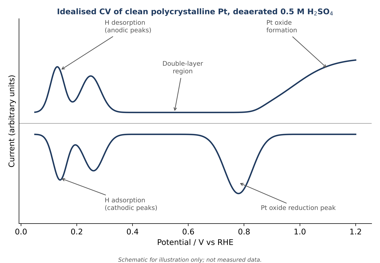
6. Carbon beyond glassy carbon: paste and fibre
"Carbon" covers materials with very different behaviour. Glassy carbon is the dense, polishable option. Two others serve needs it cannot.
Carbon paste: renewable and modifiable
A carbon paste electrode is a mixture of conductive carbon particles and a binder packed into a cavity, so the surface can be renewed by extruding and smoothing a fresh layer. That makes it attractive in three situations: when the surface fouls quickly and polishing is impractical, when you want to mix a modifier (an enzyme, a complexing agent, a catalyst) into the bulk of the electrode, and when you want a low-cost way to prototype a sensor.
The trade-offs are mechanical and chemical. The paste is mechanically delicate and can be unsuitable for demanding flow configurations. Many conventional binders are incompatible with some organic solvents, although specialised carbon-paste formulations can be prepared for non-aqueous media. Confirm the binder and solvent compatibility for the specific electrode before use. The ScienceGears carbon paste electrode is listed in 2, 3 and 5 mm diameters with a PTFE coat. The product page does not state the binder composition, so confirm that with the technical team if your modifier or solvent could interact with it.
Renewal is the point, but consistency is the discipline. Pack the paste to the same density each time, smooth it on clean paper to a flat face, and record how you did it. Reproducibility can depend on packing density, carbon and binder composition, modifier distribution and the surface-renewal procedure.
Carbon fibre: very small, very fast
A single carbon fibre of 5 or 7 µm diameter sealed in an insulating body gives a micro-disc or short micro-cylinder with a carbon surface. At this size currents are in the picoampere to nanoampere range, the electrode responds quickly, and it can be positioned in very small volumes. These properties are why carbon fibre electrodes are associated with fast-scan cyclic voltammetry and amperometry of oxidisable biomolecules, as well as biosensor development with enzyme or film modification. The carbon fibre microelectrode page lists both diameters. Section 8 explains what the diameter implies for the signal you will see.
Where graphite fits
Graphite rods and plates are also available from ScienceGears, but they are bulk electrode materials rather than precision voltammetric discs, and they sit outside the scope of this guide. For flat catalyst or electrolysis work see the plate electrodes and rod electrodes pages.
Choose carbon paste for renewable, modifiable surfaces, generally in aqueous media unless the actual paste formulation has been validated for the intended solvent. Choose carbon fibre when the volume, the time scale or the current level demands micron-scale dimensions and a carbon surface.
7. Diameter, area and current: sizing the disc before you buy it
A bigger electrode gives a bigger current, and a bigger current is not automatically better. Diameter controls four things at once: the faradaic signal, the capacitive background, the uncompensated resistance and the practical effort of keeping the surface clean. Each can be estimated in a few lines before you order.
Geometric area and current density
The geometric area of a disc is πr². For the standard diameters:
| Diameter | Geometric area |
|---|---|
| 1 mm | 0.0079 cm² |
| 2 mm | 0.031 cm² |
| 3 mm | 0.071 cm² |
| 5 mm | 0.196 cm² |
| 6 mm | 0.283 cm² |
| 11.28 mm | 1.00 cm² |
When you report current density, say whether it is normalised to geometric area or to real (electrochemically active) area, and say how you measured the latter.
Signal: a worked example
For a reversible one-electron couple at 25 °C, the Randles–Ševčík relation gives the peak current. Taking 1 mM analyte, a diffusion coefficient of 7 × 10⁻⁶ cm²/s and 100 mV/s, the peak current is about 1.8 µA at 1 mm, 16 µA at 3 mm and 44 µA at 5 mm. Those figures are straightforward to compare against your potentiostat's current ranges and noise floor. These examples assume 1 mM analyte; at lower concentrations, peak current decreases proportionally. For example, the predicted 1 mm peak is about 1.8 nA at 1 µM under otherwise identical assumptions, so suitable low-current ranges and shielding may be essential.
Resistance: why diameter and electrolyte interact
For a disc electrode in a large volume of electrolyte, the solution resistance close to the electrode scales as 1/(4κr), where κ is the conductivity and r the radius. In 0.1 M KCl (about 12.9 mS/cm) that is roughly 390 Ω at 1 mm diameter, 130 Ω at 3 mm and 78 Ω at 5 mm. This is an idealised access-resistance approximation, not a universal upper bound for the actual uncompensated resistance. Reference-tip placement, cell geometry and electrolyte conductivity affect the measured resistance. For comparable diffusion-controlled solution measurements, a smaller disc can carry less current and experience a smaller iR drop despite its higher access resistance; verify the conditions rather than relying on diameter alone.
The consequences become visible in two places. In a dilute electrolyte, such as 0.01 M KCl at about 1.4 mS/cm, the same 3 mm disc sees roughly 1.2 kΩ, and the 16 µA peak above then costs about 19 mV of distortion. In catalysis, where currents reach milliamperes, even 130 Ω costs tens or hundreds of millivolts. If peak separations are unexpectedly large or a Tafel plot shows an altered slope or curvature, evaluate uncompensated resistance and mass-transport effects before attributing the result solely to the electrode surface.
Practical sizing rule: estimate the expected current and uncompensated solution resistance for each candidate disc diameter. Because faradaic current and solution resistance scale differently with electrode size, a larger disc does not automatically produce a smaller iR error. For high-current catalysis, select area and electrolyte on the basis of the required current density, reaction and mass-transport conditions, and practical cell design. Measure or validate the uncompensated resistance before applying an instrument-appropriate iR-compensation method; excessive positive-feedback compensation can cause instability or oscillation.
Real area, roughness and the two reference constants
Geometric area is not electrochemically active area. Polishing history, roughening during cycling and, for catalysts, the loading all change it. For clean polycrystalline surfaces, two reference charge densities are widely used:
- Platinum: a conventional reference charge of approximately 210 µC/cm² for hydrogen underpotential deposition on polycrystalline Pt; the background-corrected hydrogen charge divided by this reference gives a method-dependent surface-area estimate, not a universal absolute area.
- Gold: a commonly used reference charge of approximately 390 µC/cm² for gold-oxide reduction, likewise providing a method-dependent surface-area estimate under an appropriate oxidation/reduction protocol.
Both figures appear throughout the published characterisation literature. Treat the results as method-dependent estimates: the numbers depend on the integration limits, background subtraction, electrolyte and surface structure. The ratio of real to geometric area, the roughness factor, is a useful quality indicator. A reported roughness factor for a particular polished platinum electrode should not be treated as a universal acceptance range. Interpret your result using the same electrode, electrolyte, integration method and a reproducible baseline; a sustained increase may indicate surface roughening or a change in the measurement basis.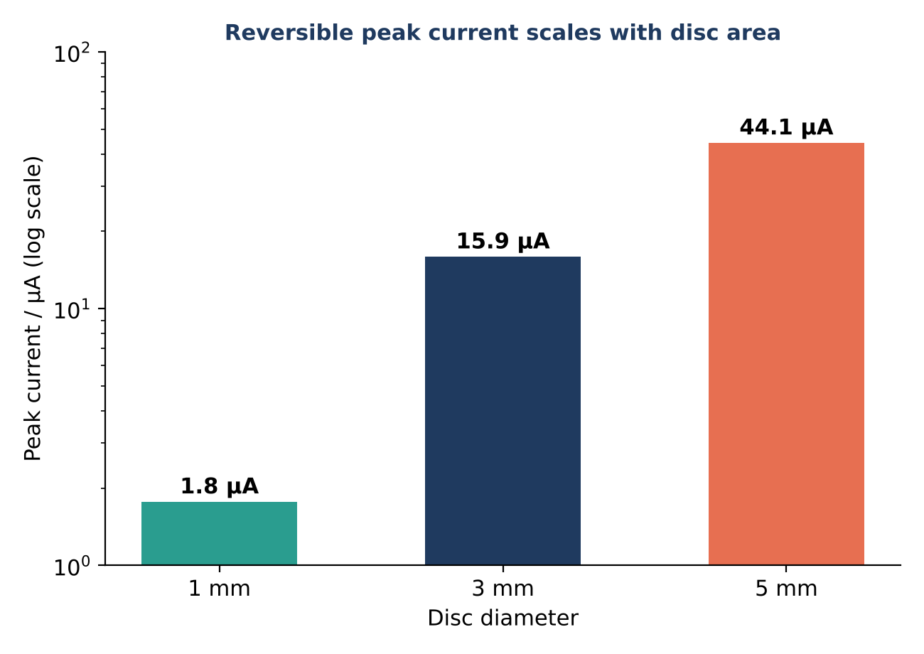
ScienceGears also has convenient sizing options built into the disc electrode range: small discs (0.5 to 2 mm) for low-volume or high-resistance cells, mid-sized discs (3 to 5 mm) as the general-purpose range, and the 11.28 mm glassy carbon disc for work normalised to 1 cm². For the potentiostat end of the problem, see the potentiostat range.
8. Microelectrodes: when smaller is better
For a microdisc, the relative importance of planar and radial diffusion depends on electrode radius and experiment time scale (or voltammetric scan rate). At sufficiently slow scan rates, radial transport can dominate, allowing the response to approach a steady-state, sigmoidal voltammogram; there is no single diameter at which this occurs in every experiment. IUPAC's technical report on microelectrodes lists the consequences: reduced ohmic drop, fast establishment of a steady-state signal, and a much smaller charging current relative to the faradaic signal.
For an ideal flush, inlaid microdisc under steady-state diffusion control, the limiting current is i = 4nFDCr. At 1 mM, D = 7 × 10⁻⁶ cm²/s and n = 1, the calculated values below illustrate that geometry for nominal diameters in the ScienceGears microelectrode range. A protruding carbon-fibre tip or another non-flush geometry may give a different limiting current:
| Diameter | Steady-state current | Characteristic scan-rate estimate (scan well below for near steady state) |
|---|---|---|
| 5 µm (carbon fibre) | 0.7 nA | about 3 V/s |
| 7 µm (carbon fibre) | 1.0 nA | about 1.5 V/s |
| 10 µm | 1.4 nA | about 0.7 V/s |
| 25 µm | 3.4 nA | about 0.1 V/s |
| 50 µm | 6.8 nA | about 30 mV/s |
| 100 µm | 14 nA | about 7 mV/s |
| 200 µm | 27 nA | about 2 mV/s |
The last column is an order-of-magnitude guide, taken from the condition that the diffusion layer thickness, √(DRT/Fv), is comparable to the radius. Scan well below it to see a clean plateau. It carries a useful correction to common assumptions: an ideal 100 or 200 µm flush disc at 100 mV/s is generally outside the near-steady-state limit for the assumed diffusion coefficient, even though it remains a microelectrode by size. The benefits listed above scale with how far below that scan rate you work, so diameter and scan rate should be chosen together.
What microelectrodes buy you
- Low-conductivity or poorly supported media. Nanoampere currents can substantially reduce iR drop in resistive media, but the remaining error depends on uncompensated resistance and must still be assessed. Some specialised microelectrode measurements can use two electrodes when the second-electrode potential and polarisation are appropriately controlled or accounted for.
- Small volumes. The diffusion field is local, so the electrode works in droplets and microcells.
- Fast kinetics. The small charging current allows scan rates where a macroelectrode would be dominated by background.
What they cost you
- Noise sensitivity. Currents of tens of picoamperes to a few nanoamperes sit near the noise floor of many setups. A Faraday cage, short shielded leads and a potentiostat with a low-current range are part of the electrode, not optional extras. The potentiostat range is the place to check current ranges.
- Fragility. The tip scratches and chips easily. Handle, store and polish accordingly.
- Limited use for high-current catalysis, where the total current is too small to measure product formation.
Choosing the material and size
ScienceGears lists platinum and gold microelectrodes at 10, 25, 50, 100 and 200 µm, a nickel microelectrode at 50 or 100 µm for nickel-relevant alkaline chemistry, and the carbon fibre microelectrode at 5 or 7 µm. Platinum and gold follow the logic of Sections 4 and 5. Nickel suits alkaline systems where nickel itself is the active surface. Carbon fibre suits oxidisable biomolecules and fast-scan work.
For size, start from the technique. For a near-steady-state plateau at 10–50 mV/s, a small flush microdisc (often around 10–25 µm) may be suitable, but verify the voltammogram at the intended scan rate, diffusion coefficient and electrode geometry. If you want microelectrode behaviour with a measurable current on an ordinary potentiostat, 25 to 50 µm is the compromise. Consider 100–200 µm microdiscs when a higher total current or a more robust tip is useful, recognising that near-steady-state behaviour may require much slower scans.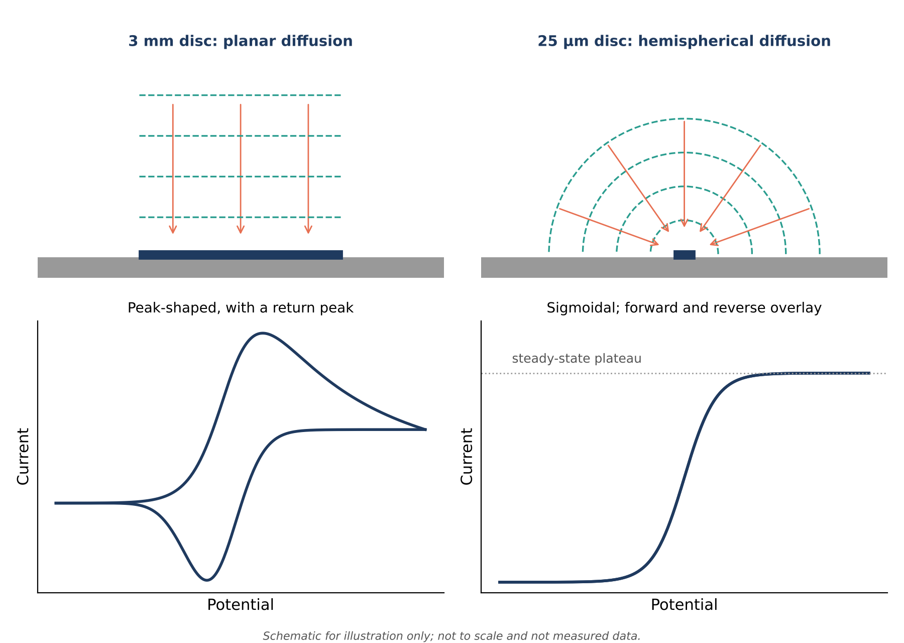
9. Format and geometry: disc, L-type, rod, plate and rotating
Once material and size are decided, the geometry decides how the electrode sits in the cell and how mass transport is controlled.
- Straight disc (stationary). The default. A flat polished face in an insulating body gives a reproducible area and a diffusion field you can model. Choose it for CV, EIS and most kinetics.
- L-type. The angled body can make it easier to orient the active face and position the reference-electrode sensing tip in constrained cells. Any reduction in iR depends on the actual WE–reference-tip geometry and electrolyte conductivity, rather than on the L-shaped format alone. It is also convenient for spectroelectrochemical cells where the face has to point in a particular direction. The ScienceGears L-type electrodes are 2, 3 and 5 mm, which makes them macroelectrodes, not microelectrodes.
- Rod. A glassy carbon or graphite rod of 3 to 6 mm with an 80 mm active length is designed for immersion, so the exposed area is a lateral surface plus the end. Use it when you want a robust probe, not a defined planar area.
- Plate or sheet. A larger flat area for bulk electrolysis and higher-current work. Area is defined by the immersed length or by a clamp, so reproducibility depends on how consistently it is mounted. The electrode clamp and holder options help here.
- Rotating disk. When you need to separate kinetics from mass transport, a rotating disk gives a defined hydrodynamic regime. ScienceGears lists glassy carbon, gold and platinum rotating disk electrodes, as well as ring-disk combinations, on the RDE and RRDE page. The glassy carbon version has a 5 mm standard disc. Check the product pages for the diameters of the other variants, and treat the rotating-disk analysis itself as a separate topic beyond this guide.
A final geometry note: the face is the electrode. A beautifully chosen material in a body that leaks, a bubble that clings to the face, or a loose connection shows up as noise that looks like a surface problem. Mount the electrode firmly, keep the face vertical or tilted to shed bubbles, and keep the reference capillary tip close but not touching.
10. Preparation and electrolyte compatibility
Choosing correctly and then preparing carelessly gives worse data than choosing adequately and preparing well. Two habits do most of the work.
Polish to a defined routine and verify electrochemically. The sequence is 1.0, 0.3, then 0.05 µm alumina on separate pads, rinsing between grits, with abrasive paper only for visible scratches or films. For day-to-day use a brief 0.05 µm touch-up is usually enough. Verification depends on the material: ferri/ferrocyanide for glassy carbon (compare against your own validated baseline), hydrogen underpotential deposition in deaerated 0.5 M H₂SO₄ for platinum, and the oxide reduction peak in dilute H₂SO₄ for gold. The full protocol, including pad handling, sonication and what to do when the check fails, is in the dedicated polishing and maintenance guide.
Run a blank before every new electrolyte. A blank CV in the supporting electrolyte helps assess the practical window and capacitive background and may reveal electroactive contamination. Save it with the data.
The compatibility table below summarises the qualitative picture. It is a starting point, and the blank scan is the arbiter.
| Electrolyte class | Glassy carbon | Gold | Platinum | Carbon paste |
|---|---|---|---|---|
| Strong acid (H₂SO₄, HClO₄) | Good, wide window | Limited anodic window | Good; hydrogen region useful for diagnostics | Usable; paste is mechanically delicate |
| Alkaline (NaOH, KOH) | Good | Usable, observe oxide behaviour | Usable; window per IUPAC table above | Usable; verify binder stability |
| Neutral buffers | Good general choice | Good for thiol chemistry | Watch for adsorption of buffer species | Usable |
| Non-aqueous (acetonitrile, DMF) | Commonly used | Usable with care | Commonly used | Binder-dependent; confirm non-aqueous compatibility |
| Chloride-rich, strongly anodic | Check blank | Check blank, practical limit may be lower | Check blank | Check blank |
The insulating body matters for non-aqueous work. The disc electrodes use a PTFE coat, chosen for chemical resistance, and the glassy carbon rotating disk electrode is built in PTFE or PEEK. If your solvent is aggressive, confirm compatibility of the body, and of any seals, with the technical team before ordering.
A note on scope
This guide covers glassy carbon, gold, platinum, carbon paste, carbon fibre and the metal microelectrodes as stationary working electrodes. It does not cover mercury and mercury-film electrodes, boron-doped diamond, rotating-disk hydrodynamic analysis, metal foam or mesh electrodes, or disposable sensors. For screen-printed formats see the screen-printed electrode selection guide, and for foam electrodes see the guide to metal foam electrodes for electrocatalysis.
11. Decision matrix: working electrode by application
Use this table to go from application to material, product and the main constraint to check. Every product name links to its page.
| Application | Recommended material or format | Specific product | Key rationale | Key constraint |
|---|---|---|---|---|
| General aqueous CV or LSV of a solution couple | Glassy carbon disc, 3 mm | GC disc electrode | Wide window, low background | Polish to the same routine each run |
| Catalyst ink drop-cast for activity screening | Glassy carbon disc, 3 to 5 mm | GC disc electrode | Low intrinsic activity, mirror finish for uniform films | Anodic excursions change the surface |
| Current-density work normalised to 1 cm² | Glassy carbon disc, 11.28 mm | GC disc electrode | Geometric area of 1.00 cm² | Larger disc needs more current range and uniform polishing |
| Low-volume or resistive cell, solution couple | Glassy carbon or gold disc, 1 to 2 mm | Disc electrode | Lower total current and often smaller iR drop, despite higher access resistance | Low current needs a quiet setup |
| Tight cell, reference probe access | L-type, 2, 3 or 5 mm | L-type working electrodes | Allows reference-tip access in tight cells | Protect the angled body during polishing |
| Hydrogen evolution, oxygen reduction, platinum benchmarking | Platinum disc, 3 to 5 mm | Platinum disc electrode | Reference surface, verifiable by hydrogen region | Short cathodic window in water |
| Higher-current Pt work, bulk electrolysis | Platinum plate | Platinum plate sheet | Flat Pt surface; select purity grade and define immersed or clamped area | Area control depends on mounting |
| Thiol self-assembly, gold-bound biosensing | Gold disc, 2 to 3 mm | Gold disc electrode | Gold–sulfur chemistry | Limited anodic window, soft surface |
| CO₂ reduction on a gold surface | Gold disc or gold RDE | Gold rotating disk electrode | Gold surface chemistry, controlled transport | Confirm disc diameter with the technical team |
| Renewable surface, bulk-modified sensor prototype | Carbon paste, 2, 3 or 5 mm | Carbon paste electrode | Surface renewed by repacking | Confirm binder/solvent compatibility; mechanically delicate |
| Kinetics separated from mass transport | Rotating disk, glassy carbon or platinum | GC RDE and Pt RDE | Defined hydrodynamics | Match the shaft fitting to your rotator |
| Steady-state voltammetry in dilute or resistive media | Platinum microelectrode, 10 to 25 µm | Platinum microelectrode | Radial diffusion at suitable scan rate; often reduced iR drop | Nanoampere currents need shielding |
| Gold-surface chemistry at the microscale | Gold microelectrode, 10 to 50 µm | Gold microelectrode | Small volume, fast response | Fragile tip, careful polishing |
| Alkaline, nickel-relevant micro-scale work | Nickel microelectrode, 50 or 100 µm | Nickel microelectrode | Nickel surface at micro-scale | At 100 µm, not steady state at routine scan rates |
| Fast-scan detection of oxidisable biomolecules | Carbon fibre, 5 or 7 µm | Carbon fibre microelectrode | Small size, fast response, carbon surface | Picoampere to nanoampere currents |
| Extended immersion or flexible cell layouts | Glassy carbon rod, 3 to 6 mm | Rod electrodes | Robust probe, long active length | Exposed area less defined than a disc |
| Routine surface renewal across GC, Pt and Au | Polishing consumables | Electrode polishing kit | Full coarse-to-fine alumina sequence | Dedicate pads per grit and per material |
12. Frequently asked questions
Which working electrode should I use for cyclic voltammetry of a new redox couple?
Start with a 3 mm glassy carbon disc. It has a wide window, a low background, and no strong chemical preference. Run a blank in your electrolyte, polish to a fixed routine, and only move to platinum or gold if the chemistry calls for a metal surface or if the glassy carbon background interferes.
Should I use glassy carbon, gold or platinum for hydrogen evolution studies?
Platinum is the standard benchmark surface, and its hydrogen region lets you verify cleanliness and estimate real area. Glassy carbon is the usual support when you want to measure a catalyst deposited on top, because it contributes little activity of its own. Gold is a poor hydrogen evolution catalyst by comparison and is chosen when its different behaviour is the point.
What electrode diameter should I choose?
For a solution couple in a supported electrolyte, 3 mm is a good default: roughly 16 µA peak current for 1 mM at 100 mV/s under the assumptions in Section 7, which sits well above the noise floor of an ordinary potentiostat. Go to 1 to 2 mm for small volumes or resistive media, and to 5 mm or more when you need more current or an easier surface to polish. Microelectrodes also include larger micron-scale diameters; achieving a near-steady-state response depends on diameter, scan rate, diffusion coefficient and geometry.
When is a microelectrode better than a standard disc?
When the medium is resistive or poorly supported, when the volume is very small, or when you need fast scan rates with low charging current. The price is nanoampere signals that need shielding and a quiet instrument. Choose the diameter together with the scan rate, since a 200 µm disc at 100 mV/s is not at steady state.
How do I measure the real area of my electrode?
Estimate it from a reference surface process. On platinum, integrate the hydrogen adsorption or desorption charge in acid and divide by 210 µC/cm². On gold, integrate the oxide reduction peak in dilute sulfuric acid and divide by 390 µC/cm². Both are method-dependent estimates, so state your integration limits and background correction, and report the roughness factor alongside.
Can I use a carbon paste electrode in organic solvents?
Not without confirming the carbon-paste formulation. Many conventional paste binders deteriorate in organic solvents, but specially formulated carbon-paste electrodes have been used in non-aqueous media. For the ScienceGears electrode, request the binder composition and chemical-compatibility guidance; glassy carbon or a suitable metal electrode is often a more straightforward alternative.
13. Expert support: how ScienceGears works alongside your research
Electrode selection goes faster with someone who has run these materials at the bench. A PhD-trained electrochemist with direct experience of glassy carbon, gold and platinum working electrodes across catalysis, sensing and corrosion research leads ScienceGears, and that background shapes how the technical team supports every electrode order, from a first 3 mm disc to a microelectrode set-up for a resistive medium.
Electrode selection before you order
If you are unsure which material, diameter or format suits your electrolyte, current range or cell volume, the technical team will work through the window, area and iR estimates with you before you commit. Talk to our technical team →
Surface and electrolyte compatibility check
Describe your electrolyte, potential range and technique, and the team will flag which materials and insulating bodies are likely to cause trouble, and which blank scans to run first.
Complete system supply
- Disc working electrodes (glassy carbon, gold, platinum and metals)
- Microelectrodes (platinum, gold, nickel and carbon fibre)
- Carbon paste electrodes
- L-type working electrodes
- RDE and RRDE electrodes
- Electrode polishing kit
- Reference electrodes and counter electrodes
- Electrode clamp and holder
- Faraday cage for electrochemical measurements
- Potentiostats and galvanostats
Stock availability and dispatch
ScienceGears supplies working electrodes, polishing accessories and related electrochemistry consumables to customers in Australia and New Zealand. Availability varies by product and configuration; contact the team to confirm current stock, delivery location and the expected dispatch date before ordering.
"Choose the electrode for the window and the surface chemistry first, size it from the current you expect, and let a blank scan tell you whether you were right."
14. Further reading
- How to polish and maintain glassy carbon, gold and platinum electrodes
- How to select a counter electrode
- How to choose the right reference electrodes
- Electrochemical cell selection guide
- Introduction to electrochemical techniques
- Working electrode range
- Microelectrodes
- For the formal definitions behind Section 8, see the IUPAC technical report on microelectrodes (Pure and Applied Chemistry, volume 72, 2000): IUPAC technical report
15. Get in touch
If you are choosing a working electrode for a new technique, sizing a microelectrode set-up for a resistive medium, or reordering consumables before your next run, the ScienceGears technical team is available to help.