

1. The instrument decision researchers get wrong most often
Most electrolyser research programmes begin the same way: a researcher with an excellent catalyst, a working H-cell or small MEA cell, and a standard potentiostat already on the bench. The first polarisation curve looks promising. The next question is how to push to higher current density, larger active area, and longer durability tests and that is where the instrument decision typically stalls.
The options available standard potentiostat, power potentiostat, current booster, dedicated test station, industrial power supply are rarely explained as a continuous decision framework. Each tends to be presented in isolation: the potentiostat vendor shows you how it handles low-current catalyst screening; the test station vendor shows you how their integrated system manages a full stack. The middle ground what happens between small-cell screening at milliamps and full-station operation at tens of amps is where most research programmes actually live, and where the instrument selection is least clearly supported.
This guide maps the entire range in one place. The decision at each level depends on three variables: the current the experiment requires, whether EIS capability is needed alongside DC power, and how much balance-of-plant infrastructure the experiment demands. Getting these three variables right defines the correct instrument at every stage of electrolyser development.
All instruments and test stations discussed are available from ScienceGears with local AU/NZ support, installation, and commissioning.
2. The four levels of electrolysis testing and what separates them
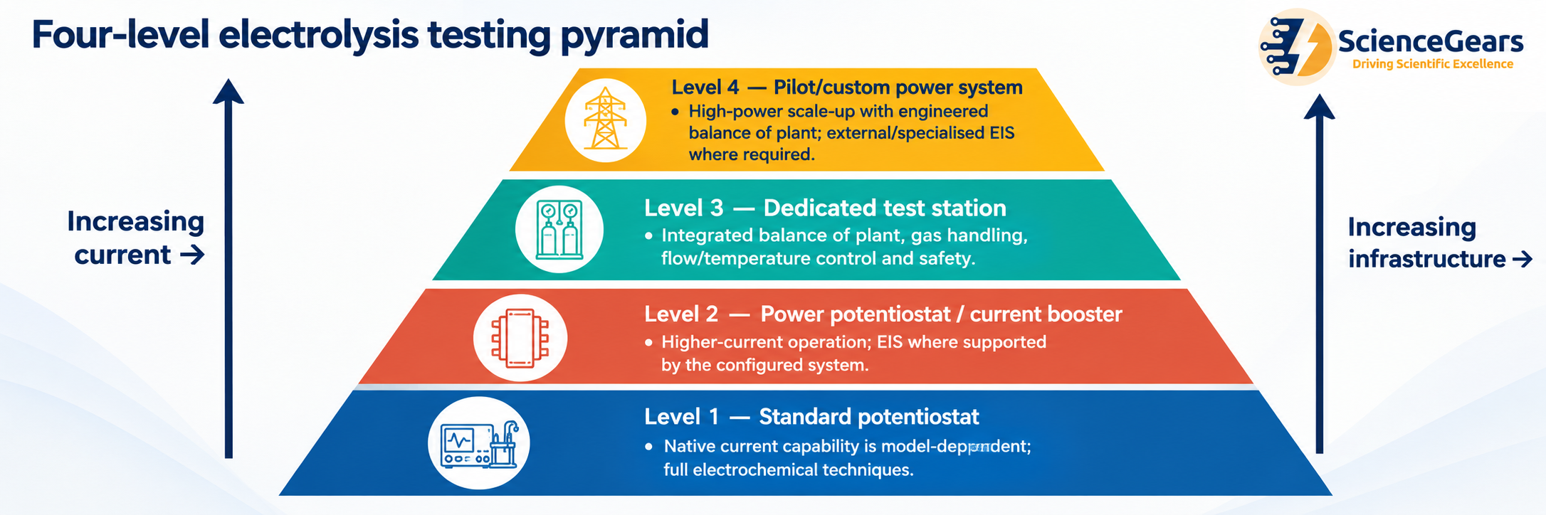
Caption: The four levels of electrolysis testing form a continuous progression from fundamental catalyst screening to pilot-scale validation. Each level transition is triggered by a specific current threshold or infrastructure requirement — not by researcher preference or budget alone.
2.1 What triggers a level transition
Three variables drive the transition from one level to the next:
Current: The current required is the primary selector. A research potentiostat's native current limit is model-dependent, ranging from hundreds of milliamperes to a few amperes. Calculate the required total current from active area × target current density, then confirm the potentiostat's current, voltage compliance, and power limits. A current booster extends this to ±20–100 A, covering most single MEA cell active areas at research-relevant current densities. A dedicated test station handles the same current range but adds the gas handling, flow management, and safety interlocks that continuous high-current operation requires. Industrial power supplies operate above these ranges for stack and pilot validation.
EIS requirement: EIS at high current requires the instrument to superimpose a small AC perturbation on a large DC current a capability that standard potentiostats provide at milliamp-level currents, but that requires specialist hardware at ampere-level currents. Not all current boosters preserve EIS capability; not all test stations include integrated impedance. If EIS is needed alongside high-current DC operation, the instrument specification must be confirmed explicitly.
Balance of plant: At low current in an H-cell or small MEA, the researcher manages water supply, temperature, and gas manually. At higher current density over longer durations, these variables become unmanageable without automated infrastructure water management, pressure control, temperature regulation, gas handling, and safety interlocks. The dedicated test station is the instrument that provides this infrastructure; below that level, the researcher provides it manually or through custom-built peripheral hardware.
3. Level 1 — Standard potentiostat: small cell, catalyst screening, H-cell
3.1 What standard potentiostats provide
A potentiostat is an electronic control instrument that controls the potential between the working electrode and the reference electrode in an electrochemical cell and measures the resulting current. In the context of electrolysis research, the standard potentiostat is the appropriate instrument when the experiment is in the catalyst screening and fundamental characterisation phase — working with small active areas, low total current, and a need for the full suite of electrochemical techniques.
Standard research potentiostats typically provide:
- Native current output: ±100 mA to ±1 A depending on model and current range setting
- Voltage compliance: ±5 V to ±20 V depending on model
- Full technique support: LSV, CV, chronoamperometry, chronopotentiometry, EIS, OCP, galvanostatic EIS
- Three-electrode cell control with high-accuracy potential measurement against a reference electrode
Biosensors and trace electroanalysis often require nA–µA measurement capability, coin cells commonly operate in the mA range, and larger cells or electrolysers may require amps to tens of amps. Most potentiostats provide multiple ranges with auto-ranging to balance resolution and accuracy — the key is matching the instrument's ranges and compliance limits to your expected operating conditions.
3.2 Electrolysis experiments correctly scoped for Level 1
- H-cell studies: Linear sweep voltammetry for HER or OER catalysts, screening overpotential at small working electrode area (≤ 1 cm² disc). Total current at 10 mA/cm² on a 3 mm disc electrode ≈ 0.7 mA well within standard potentiostat range
- Rotating disc electrode (RDE) OER/HER screening: Catalyst-coated disc electrodes typically 0.196 cm² (5 mm Ø); total current even at 100 mA/cm² ≈ 20 mA standard potentiostat range
- CV and LSV in half-cell configuration: Measuring onset potential, Tafel slope, exchange current density of catalyst inks on carbon paper or metal foam at small geometric area
- EIS at low current density: Measuring charge transfer resistance, double-layer capacitance, and solution resistance at the catalyst interface in the mA regime
- Chronoamperometric stability testing: Holding potential at a fixed overpotential for up to several hours at small active area
3.3 When Level 1 becomes insufficient
The standard potentiostat reaches its limit when:
- The required total current, calculated from active area × target current density, approaches or exceeds the potentiostat's rated current, voltage-compliance or power limit.
- The experiment moves from a three-electrode H-cell to a two-electrode MEA configuration requiring higher voltage headroom
- The experiment requires extended high-current holds that saturate the potentiostat's output stage, causing thermal shutdown or current limiting
- The target current density exceeds what the potentiostat's maximum output can sustain across the electrode area
4. Level 2 — Power potentiostat and current booster: MEA cell, single cell
4.1 The current booster — what it adds
Current boosters extend the output range of potentiostats for high-current applications such as electroplating and industrial electrolysis. Standard potentiostats often have limited current output of typically a few amps. Current boosters allow researchers to perform experiments requiring higher currents — 20 A, 30 A, 100 A — essential for large-format batteries, fuel cells, or industrial electrolysis.
A current booster or high-current power extension increases the current and power capability of a compatible potentiostat or electrochemical control system. The exact control architecture, measurement accuracy, EIS bandwidth and software integration depend on the booster and host-instrument combination. These specifications should therefore be confirmed for the complete configured system rather than assumed to be identical to those of the base potentiostat.
High-current extensions are available in a range of current ratings, from tens of amperes to 100 A and beyond depending on model and configuration. EIS capability, usable frequency range, parallel operation, software integration and supplied connection hardware are model-specific and should be confirmed from the relevant datasheet.
Voltage compliance: typical voltage ranges from ±5 V to ±48 V depending on the booster model.
4.2 The power potentiostat — an integrated alternative
The PP212 is a 4-quadrant power potentiostat designed to apply and sink high currents up to ±10 A at a high voltage range of up to ±20 V, with a maximum power output of 200 W. For medium power applications, the PP212 is used as an extension of a modular potentiostat series. Most electrochemical techniques which can be performed with the main potentiostat can also be carried out with the extended power potentiostat PP212 setup. Besides an extension, the PP212 power potentiostat can also be used in stand-alone mode for standard DC measurements such as charging and discharging of batteries.
The PP212 is an external 4-quadrant power potentiostat that can extend an IM7/ZENNIUM potentiostat for higher-power electrochemical measurements. It can also operate independently for standard DC measurements. With a maximum current of ±10 A, voltage range of ±20 V and maximum output power of 200 W, the usable MEA active area depends directly on the target current density. For example, 10 A corresponds to 10 cm² at 1 A/cm² or 5 cm² at 2 A/cm².
4.3 Electrolysis experiments correctly scoped for Level 2
- Single MEA cell polarisation curves (1–25 cm² active area): PEMWE at 1–3 A/cm², a 5 cm² active area requires 5–15 A total — within a ±20 A booster range
- MEA conditioning protocols: Sustained current or voltage holds may require continuous high-current delivery for many hours. The conditioning setpoint and duration should follow the specific MEA or validated test protocol.
- EIS at operating current density: Superimposing AC perturbation on the DC operating current for high-frequency resistance (HFR) measurement and Nyquist analysis — requires a booster with confirmed EIS bandwidth
- Galvanostatic EIS (GEIS): Controlling the DC current precisely whilst running the AC sweep — important for PEMWE where potential control is less natural than current control
- Short-duration durability holds: Fixed-current operation for hours to days on a MEA test cell — possible with a booster if water and temperature are managed manually or with simple peristaltic pump and hotplate
4.4 When Level 2 becomes insufficient
The booster-potentiostat combination reaches its practical limit when:
- The active area or stack size requires currents above the booster's maximum rating (above 100–150 A for parallel-booster systems)
- Continuous operation over days to weeks requires automated balance-of-plant control that a manually managed peripheral setup cannot reliably provide
- Gas safety requirements specifically hydrogen crossover monitoring, automated purge protocols, and interlocked shutdowns on gas threshold exceedance cannot be met by manual management
- Pressure control is required above ambient for the electrolysis operation
5. Level 3 — Dedicated test station: single cell and small stack with balance of plant
5.1 What a dedicated test station adds beyond the booster
Electrolyser test stations provide a controlled environment for studying water electrolysis and hydrogen production. They combine precision power electronics, flow and pressure control, gas handling and data acquisition so researchers can safely operate single cells or small stacks over a wide current and voltage range. Stable control of temperature, humidification and gas composition is essential for obtaining reproducible performance and durability data.
The dedicated test station is not simply a higher-current potentiostat. It is a complete research infrastructure — the power electronics, flow management, gas handling, safety interlocking, and data acquisition all integrated in a single engineered system. The distinction from a booster-potentiostat at Level 2 is not primarily current range (some boosters reach 150 A, which overlaps with single-cell test station current ranges) it is the infrastructure surrounding the power electronics.
AEMWE test stations often sit alongside broader electrochemistry and gas-handling workflows. Many labs pair test stations with potentiostat/EIS tools for diagnostics for example, resistance trends and dynamic response and with gas analysis for purity or crossover verification, depending on the research question.
What the test station provides that a booster cannot:
- Automated electrolyte circulation with temperature control and level monitoring
- Gas conditioning with condensation traps, cooling, and liquid-gas separation
- Automated purge and sequencing logic including inert purge before startup and emergency purge on fault condition
- Gas crossover monitoring with safety interlocked shutdown on H₂-in-O₂ or O₂-in-H₂ exceedance
- Pressure control for pressurised electrolysis variants
- Integrated data logging of temperature, pressure, flow, current, voltage, and derived parameters (efficiency, hydrogen production rate)
5.2 PEMWE test stations
PEM water electrolyser test stations provide controlled operating conditions to evaluate proton exchange membrane electrolysis cells and stacks for hydrogen production. These systems regulate power, water management, gas handling and safety interlocks while logging performance data for research, validation and pilot-scale development. Suitable for university labs through to industrial R&D, they help standardise testing across single-cell and multi-kilowatt stack platforms.
Many PEMWE programmes benefit from impedance (EIS) to separate ohmic, kinetic, and mass-transport contributions and to monitor degradation mechanisms over time. Some test stations offer integrated impedance capability as an option; alternatively, workflows may combine station operation with external electrochemical instrumentation depending on the measurement approach and electrical configuration.
For PEMWE test stations specifically: deionised water is supplied to the anode; the membrane conducts protons; hydrogen is produced at the cathode. At high current density, water quality and temperature control are important for obtaining reproducible PEMWE data. Pressure control is additionally required where the test protocol specifies controlled or pressurised operation; ambient-pressure testing does not require active back-pressure control.
5.3 AEMWE test stations
AEMWE test stations provide a controlled platform to operate AEM electrolysis single cells and stacks under repeatable conditions. These systems typically include electrolyte circulation with temperature control, level control and alarms, gas handling with cooling and condensation traps, automated purge and sequencing logic, and gas crossover monitoring.
AEMWE electrolyte and water-management requirements depend on the membrane, cell architecture and operating protocol. Where an alkaline supporting electrolyte is used, its concentration, temperature and exposure to atmospheric CO₂ should be controlled and recorded during extended testing because changes in these variables can affect reproducibility. Dedicated circulation and monitoring become increasingly valuable for long-duration experiments.
5.4 AlkalineWE test stations
Alkaline water electrolysis uses liquid KOH or NaOH electrolyte with a porous diaphragm, is commercially mature, and can offer lower capital cost, but typically operates at lower current density conventional systems at 0.2–0.4 A/cm², though advanced designs push considerably higher and requires more complex electrolyte management.
AlkalineWE test stations require the most extensive electrolyte management infrastructure of the three technologies concentrated KOH at 60–90 °C, with the high viscosity and evaporation rate of hot concentrated alkali making manual management impractical for sustained operation. The test station's integrated electrolyte loop, level control, and temperature management are the components that make alkaline electrolysis research reproducible at the single-cell and stack level.
5.5 When Level 3 becomes insufficient
A dedicated test station reaches its practical limit when the required current, voltage, power, thermal load, liquid and gas flow, pressure capability, or facility integration exceeds the configured station envelope. High-power test stations can extend well beyond multi-kilowatt scale, so the transition to a custom pilot-scale power and balance-of-plant system should be based on the actual test-station specification rather than on a fixed power threshold.
6. Level 4 — Industrial power supply or e-load: scale-up and pilot validation
6.1 What industrial power supply adds
At pilot and pre-commercial stack scale active areas above 1,000 cm², currents above several hundred amperes, powers in the kilowatt to megawatt range neither a booster-potentiostat combination nor a research-grade test station provides the power electronics required. Industrial DC power supplies or programmable electronic loads (e-loads) become the correct power instruments.
For scaled-up systems, a dedicated power supply may be required beyond the potentiostat's current range. Potentiostats are used in research settings for alkaline water electrolysis studies, particularly to assess electrocatalyst performance for hydrogen and oxygen evolution reactions however, for scaled-up systems, a dedicated power supply may be required beyond the potentiostat's current range.
What industrial power supplies offer:
- Current ranges from hundreds to thousands of amperes
- Power outputs from tens of kilowatts upward
- Basic voltage and current setpoint control
- Simpler data logging: voltage, current, power, and derived efficiency
What industrial power supplies do not offer:
- Reference electrode input; two-electrode operation only (no potential control vs a stable reference)
- High-quality EIS the measurement circuitry in a research potentiostat is fundamentally different from the control electronics in an industrial power supply; EIS on a stack at Level 4 requires a dedicated impedance measurement instrument connected in parallel, not built into the power supply
- High-resolution current measurement at the milliampere level industrial supplies are calibrated for high-power accuracy, not the micro-to-milliampere sensitivity a research potentiostat provides
- The safety interlocks and automated sequence logic of a dedicated test station these must be engineered separately for the pilot facility
6.2 The e-load — for fuel cell and discharge testing
A programmable electronic load (e-load) is the power instrument used when the cell or stack is a power source (fuel cell, battery) rather than a power consumer (electrolyser). In an e-load, the instrument sinks current from the device under test rather than supplying it — the equivalent of a programmable resistor that can simulate real-world load profiles.
For research programmes that include both electrolysis and fuel cell testing on the same hardware for example, reversible fuel cells or hydrogen storage-and-use cycle testing an e-load paired with an industrial power supply covers both operating modes in a way that a potentiostat or booster cannot at this power level.
7. EIS at high current why it matters and what it requires
EIS measurement at the actual operating current density of an electrolyser is qualitatively different from EIS at open circuit or low current and it is the version that provides the most diagnostically useful data. At operating current density, EIS separates the ohmic resistance (membrane HFR), the charge transfer resistance (catalyst layer kinetics), and the mass transport resistance (water and gas diffusion) from the total cell impedance in the conditions that actually reflect the cell's operating state.
Many current boosters are designed to support EIS measurements at high currents with bandwidths up to hundreds of kHz, enabling detailed kinetic and impedance analysis under realistic operating conditions.
What EIS at high current requires in the instrument:
- AC superposition capability: The instrument must superimpose a sufficiently small AC perturbation on the DC operating point while maintaining an approximately linear response and adequate signal-to-noise ratio. A 5–10 mV voltage perturbation is commonly used for potentiostatic EIS, while the appropriate galvanostatic current amplitude should be confirmed for the cell, operating point and instrument.
- Sufficient bandwidth: The frequency range for MEA EIS typically extends from 100 kHz (HFR extraction) down to 0.01–0.1 Hz (mass transport). The booster or power potentiostat must maintain phase accuracy across this range at the operating current
- Galvanostatic EIS (GEIS) mode: In electrolysis, controlling the DC (galvanostatically) is more natural than controlling potential GEIS is the standard mode for in-operando EIS on electrolysers, and not all high-current instruments implement it
Some test stations offer integrated impedance capability as an option; alternatively, workflows may combine station operation with external electrochemical instrumentation depending on the measurement approach and electrical configuration.
8. Compliance voltage the specification most researchers overlook
Compliance voltage is the maximum voltage the instrument can apply to maintain the requested current or potential under load. If the cell resistance is high, the required voltage can exceed compliance and the instrument will no longer hold the setpoint accurately. This matters for high-resistance electrolytes, membranes, low-conductivity solutions, and high-current operation where iR drop can be significant.
In electrolysis, the compliance voltage specification matters in two specific scenarios that are easy to underestimate:
Scenario 1 — Stack testing: A single PEMWE cell operates at approximately 1.8–2.2 V. A five-cell stack requires 9–11 V at the same current density. A ten-cell stack requires 18–22 V. A potentiostat with ±5 V compliance can readily cover a typical single PEMWE cell and may also cover some two-cell configurations, although the available control margin can become small. A five-cell stack requiring approximately 9–11 V clearly exceeds a ±5 V compliance range. The compliance voltage specification must exceed the maximum expected stack voltage at the maximum operating current, with a safety margin.
Scenario 2 — High-resistance electrolytes: In AEMWE or in initial conditioning of a fresh MEA, the membrane and catalyst layer resistance is higher than at steady state. The initial voltage required to pass a given current is substantially higher than the steady-state value. If the instrument's compliance voltage is insufficient to pass the conditioning current through the initially high-resistance MEA, conditioning cannot proceed at the intended current density.
Voltage compliance limits vary but often range from about +20 V to −2.5 V for high-current boosters, allowing full discharge cycles and accurate voltage control during experiments.
9. PEMWE vs AEMWE vs AlkalineWE does the electrolyser type change the instrument choice?
The instrument level (1–4) is determined by current, EIS requirement, and balance-of-plant needs the electrolyser technology type does not itself change the level. However, each technology has specific characteristics that affect the specification within a given level.
| Electrolyser type | Typical single-cell current density | Active area → current at Level 2 | Key instrument consideration |
|---|---|---|---|
| PEMWE | 1–3 A/cm² (up to >3 A/cm² for advanced MEAs) | 5 cm² @ 2 A/cm² = 10 A | DI water at anode; high-purity water management essential at Level 3+ |
| AEMWE | 0.5–2 A/cm² (rapidly improving) | 5 cm² @ 1 A/cm² = 5 A | Alkaline electrolyte circulation required from Level 2 if extended operation |
| AlkalineWE | 0.2–0.4 A/cm² conventional; higher for advanced designs | 25 cm² @ 0.3 A/cm² = 7.5 A | Concentrated KOH; corrosion-resistant wetted components mandatory |
For PEMWE at Level 2 (booster): the booster must be compatible with the DI water environment grounding and isolation requirements for a DI water system differ from an aqueous KOH system, since DI water's low conductivity means that stray current paths through the water supply can create measurement artefacts if the instrument's ground isolation is inadequate.
For AEMWE at Level 2: if the experiment runs longer than a few hours, the KOH concentration in the electrolyte will change as water is consumed and CO₂ absorption from air occurs making manual electrolyte management impractical for reproducible extended experiments. The transition to Level 3 (test station) is recommended earlier in the research programme for AEMWE than for PEMWE.
For PEAL test stations: PEAL refers to a configurable PEM and alkaline/AEM water-electrolyser test-station platform rather than to a hybrid electrolysis chemistry with a PEM anode and alkaline cathode. The fluid path, wetted materials, sensors and operating protocol should be configured for the specific electrolyser chemistry being tested.
10. Decision tree — which instrument for which experiment
Use this decision tree from the top, stopping at the first matching condition:
START: What is the maximum current your experiment requires?

├── Less than 1–2 A (total)
│   └── Standard potentiostat at Level 1
│       ├── Need EIS? → Any research potentiostat with EIS module
│       └── No EIS needed? → Any potentiostat/galvanostat
│
├── 1–100 A (total), and EIS is required at operating current
│   └── Power potentiostat or current booster at Level 2
│       ├── Need up to ±10 A, ±20 V? → Power potentiostat (PP212 or equivalent)
│       ├── Need ±20–100 A? → Current booster module
│       ├── Need >100 A? → Parallel booster configuration (up to 150 A)
│       └── CONFIRM: Does the booster support EIS/GEIS at your target current
│           and frequency range?
│
├── 1–100 A (total), EIS not required, BUT you need any of the following:
│   ├── Automated gas handling and crossover monitoring
│   ├── Electrolyte temperature and level control
│   ├── Automated purge / startup / shutdown sequences
│   ├── Pressure control above ambient
│   └── → Dedicated test station at Level 3
│       ├── PEMWE     → PEMWE test station
│       ├── AEMWE     → AEMWE test station
│       ├── AlkalineWE → AlkalineWE test station
│       └── Hybrid    → Contact ScienceGears technical team
│
└── Required current, voltage or power exceeds the rated envelope of the
    available Level-2 or Level-3 system, OR the pilot facility requires a
    separately engineered power and balance-of-plant architecture
    └── Custom pilot-scale / industrial power system at Level 4
        └── EIS still needed? → Pair with external impedance instrument
            connected in parallel with the power supply
11. Master decision matrix
| Experiment | Current required | EIS needed | BOP needed | Correct instrument | ScienceGears option |
|---|---|---|---|---|---|
| HER/OER catalyst screening, H-cell, 3 mm disc | < 5 mA | Yes | No | Standard potentiostat | Potentiostats/galvanostats → |
| RDE catalyst screening, 5 mm disc | < 50 mA | Yes | No | Standard potentiostat | Potentiostats/galvanostats → |
| PEMWE MEA conditioning, 5 cm² | 5–15 A | Optional | Minimal | Power potentiostat or booster | PP212 → / Current boosters → |
| PEMWE MEA polarisation curve, 5–25 cm² | 5–75 A | Yes | Minimal | Booster with EIS capability | Current boosters → |
| PEMWE single cell EIS at operating current | 5–50 A | Yes (GEIS) | Minimal | Booster with GEIS | Current boosters → |
| PEMWE MEA durability, >24 h | 5–50 A | Periodic | Full BOP | Dedicated PEMWE test station | PEMWE test station → |
| AEMWE single cell, short duration | 5–20 A | Optional | Minimal | Booster + manual KOH loop | Current boosters → |
| AEMWE single cell, extended durability | 5–50 A | Periodic | Full BOP | Dedicated AEMWE test station | AEMWE test station → |
| AlkalineWE single cell | 10–100 A | Optional | Full BOP | Dedicated AlkalineWE test station | AlkalineWE test station → |
| PEAL test-station platform — PEM / alkaline / AEM, configuration-dependent | 5–50 A | Optional | Dual BOP | Dedicated PEAL test station | PEAL test station → |
| SOEC single cell | Varies | Optional | High-T BOP | Dedicated SOEC test station | SOEC test station → |
| Small PEMWE stack (5–10 cells) | Current depends on active area × current density; cell count primarily increases required stack voltage | Periodic | Full BOP | High-power test station or custom pilot-scale power/BOP system, depending on required voltage, current, power and infrastructure. | PEMWE test station → |
| Pilot-scale stack | Current depends on active area × current density; total stack voltage increases with the number of series-connected cells | External only | Full industrial BOP | High-power test station or custom pilot-scale power/BOP system, depending on required voltage, current, power and infrastructure. | Contact technical team |
| Catalyst corrosion / degradation in PEMWE | < 5 mA | Yes | No | Standard potentiostat (half-cell AST) | Potentiostats/galvanostats → |
| PEMFC single cell (reverse — fuel cell mode) | 5–50 A | Yes | Full BOP | PEMFC test station | PEMFC test station → |
12. Frequently asked questions
For broader questions about ScienceGears products, ordering, and shipping, visit our main FAQ page.
Can I use my standard research potentiostat for MEA testing if I start with a small active area?
Yes for very small MEA active areas (1–2 cm²) at moderate current densities, a standard potentiostat operating at ±1–2 A native output is adequate for initial polarisation curves and conditioning. The practical limit is approximately 1–2 cm² at 1 A/cm². Above this, either the current limit clips the polarisation curve before it reaches the target operating region, or the potentiostat's thermal management cannot sustain the output continuously for the duration of a conditioning protocol. As a starting point for early MEA characterisation, a standard potentiostat is a legitimate tool with the explicit understanding that a booster or test station will be required as active area increases.
Does adding a current booster affect EIS quality?
It depends on the booster's design and its specified EIS bandwidth. Some boosters are purely DC devices they amplify the DC current accurately but do not transmit the AC perturbation faithfully, effectively blocking EIS capability. Others are specifically engineered for EIS-through-booster operation with bandwidths up to hundreds of kHz and guaranteed phase accuracy at operating current levels. Before specifying a booster for any application where EIS is part of the protocol, confirm explicitly with the supplier that the booster supports EIS in galvanostatic mode (GEIS) at your target operating current, and check the specified frequency range and minimum AC amplitude at that current level.
My potentiostat shows a compliance voltage of ±10 V is that enough for a single PEMWE MEA cell?
For a single MEA cell at typical research conditions (1.8–2.2 V cell voltage): yes, ±10 V compliance is more than sufficient. For a two-cell short stack operating at approximately 4–4.5 V total, ±10 V compliance provides substantial voltage headroom under normal operation. For larger stacks, calculate the maximum expected stack voltage and confirm adequate additional headroom for conditioning, transient behaviour and iR losses.
At what point should I move from a booster-potentiostat to a dedicated test station, even if the current is within the booster's range?
The trigger is infrastructure requirements, not current alone. The moment your experiment requires any of the following, a dedicated test station is the correct instrument regardless of current level: automated gas safety interlocks; electrolyte temperature control over a multi-hour or multi-day run; gas crossover monitoring with automated shutdown; pressurised operation; or reproducible startup and shutdown sequences. Attempting to manage these functions manually or through custom peripheral hardware whilst running at high current introduces variability that undermines the reproducibility of the dataset, regardless of how accurately the booster controls the electrical setpoint.
Can I run EIS on a PEMWE stack using a dedicated test station?
Some test stations offer integrated impedance capability as a confirmed option check the specific station specification. Where EIS is not integrated into the station itself, one possible approach is to interface a separate EIS/FRA or potentiostat system with the test station and its power electronics. The connection architecture is system-specific and must be explicitly approved for the particular station, power stage and impedance instrument; a simple parallel connection should not be assumed. In this configuration, the station handles the DC operating point, water management, and gas handling; the external potentiostat provides the AC perturbation and impedance measurement. Confirm with ScienceGears that the specific station and potentiostat combination you are considering are electrically compatible in this parallel configuration before purchasing both.
Is an industrial power supply an acceptable research instrument for single MEA PEMWE testing?
Yes, depending on the research objective. For full-cell PEMWE polarisation curves, conditioning and durability testing, a suitably specified programmable DC power supply or integrated test-station power stage can be appropriate. A power supply is not, however, a substitute for a potentiostat when the experiment requires EIS, high-resolution electrochemical diagnostics, or independent reference-electrode measurements. Instrument choice should therefore follow the measurement required rather than an assumption that publication-quality MEA data always requires three-electrode potentiostatic control.
13. Expert support: how ScienceGears works alongside your research
Selecting the right instrument level is the decision that determines whether your electrolysis research programme can generate the data it is designed to produce. A standard potentiostat in an experiment that needs 30 A produces a clipped polarisation curve. A current booster without EIS capability in a programme that needs in-operando impedance produces incomplete diagnostic data. A dedicated test station specified for a cell active area three times smaller than planned arrives with excess infrastructure the programme does not need for two years.
ScienceGears supports electrolysis research programmes from catalyst screening in H-cells through to pilot-scale PEMWE stack validation with hands-on experience at every level of the decision framework described in this guide. When you contact us about an instrument selection, we ask the three questions that determine the level: current, EIS requirement, and balance-of-plant need. From those answers, the correct instrument is usually unambiguous.
What expert support looks like in practice
Instrument scoping before purchase If you know your target active area, target current density, and whether EIS is required, contact us before purchasing. A single conversation covering those three parameters produces a specific instrument recommendation not a range of options to evaluate, but a direct specification that meets your research requirements.
Compliance voltage check If you are considering a booster or power potentiostat for a multi-cell configuration, we will confirm whether the compliance voltage is sufficient for your stack's expected voltage range at operating current including the higher transient voltages during conditioning of a fresh MEA before you commit to the purchase.
EIS-through-booster confirmation — If EIS at operating current is a requirement of your research programme, we will confirm whether the specific booster configuration you are considering supports GEIS at your target current level and across your required frequency range, and whether your existing potentiostat is the correct host for that booster module.
Test station configuration guidance For PEMWE, AEMWE, AlkalineWE, PEAL, and SOEC test stations, ScienceGears works with SciTech Korea to configure each station to the specific current range, pressure capability, gas analysis options, and diagnostics integration appropriate for your programme not a catalogue selection, but a configured system specified for your research objectives.
Complete electrolysis research system supply
- Potentiostats and galvanostats
- Current boosters
- PP212 power potentiostat
- PEMWE test stations
- AEMWE test stations
- AlkalineWE test stations
- PEAL test stations
- SOEC test stations
- PEMFC test stations
- MEA test cells
- Ion-exchange membranes
- Application notes
Local AU/NZ support installation, commissioning, and training
ScienceGears partners with SciTech Korea to bring proven electrolyser test stations to laboratories across Australia and New Zealand. Every test station delivered by ScienceGears includes local installation support, commissioning assistance, and operator training — not shipped from overseas and left to self-commission.
“The instrument level decision is not about budget or preference it is about whether the instrument can pass the required current, preserve EIS capability at that current, and manage the infrastructure the experiment demands. Get those three questions answered correctly at the start, and the rest of the research programme runs on its own merits.” — ScienceGears Technical Team
Further reading
Related ScienceGears blogs
- How to build, test, and optimise a membrane electrode assembly (MEA)
- Current density and voltage in PEM electrolysers: performance and cost
- Electrolyser test stations in Australia complete guide | sciencegears
- Potentiostat applications in electrochemical research complete guide
- What is MEA? Membrane electrode assembly complete guide
Related ScienceGears resources
Get in touch
Need to confirm which instrument level is correct for your active area and current density, or whether a specific booster supports EIS at your operating conditions? Contact our technical team we respond within 24 hours.
Request a quote → | Browse test stations → | About ScienceGears →