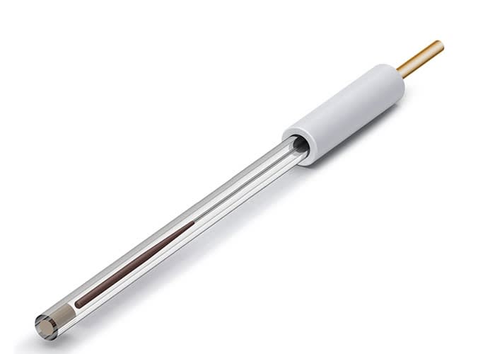


By the end of this guide you will be able to specify, order, assemble and validate a complete cyclic voltammetry (CV) bench from nothing: the potentiostat, the cell, three matched electrodes, the shielding and mounting hardware, and the polishing and electrolyte consumables. You will have a checklist with budget, standard and advanced options, a ferrocyanide benchmark that helps diagnose the setup on day one, and a decision matrix you can hand to a purchasing officer.
1. 1. The starter kit at a glance: what you need on day one
The most expensive mistake in a new voltammetry laboratory is not buying the wrong potentiostat. It is discovering, three weeks after the instrument arrives, that nothing can be connected to it: the cell has no port for the reference electrode, the working electrode has a shroud that dissolves in your solvent, or there is no polishing material and the first scan looks like a resistor. A cyclic voltammogram is a property of the whole assembly, so the kit has to be specified as a system.
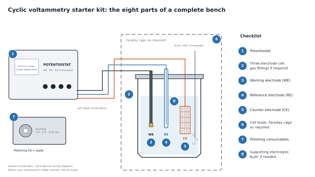
Every CV bench, whether it is a second-year teaching laboratory or an industrial R&D group, uses the same eight equipment-planning categories (with shielding and purge gas selected as required):
-
A potentiostat that can control the potential range you need and measure the currents your electrodes will produce.
-
An electrochemical cell with ports for three electrodes and suitable gas fittings where atmosphere control is required.
-
A working electrode (WE), where the reaction of interest happens.
-
A reference electrode (RE), which provides a stable potential reference.
-
A counter electrode (CE), which completes the circuit.
-
Appropriate cell leads and, where needed, shielding to limit electrical interference.
-
Polishing and cleaning consumables, because the electrode surface is a reagent.
-
Supporting electrolyte, with an inert purge gas when dissolved oxygen must be excluded.
The rest of this guide takes each item in turn, explains the decision, and maps it to products that ScienceGears lists for each role. Where a specification could not be confirmed from a live product page, it is flagged so that you can check it at the quotation stage rather than at the bench.
How the three tiers differ
Section 10 gives full kit lists. In summary:
| Budget (teaching and screening) | Standard (research group) | Advanced (method development and publication-grade work) | |
|---|---|---|---|
| Potentiostat | Portable, ±10 V; verify maximum current for exact revision; no EIS | Single-channel, ±10 V, ±2 A, EIS to 1 MHz | Bipotentiostat or multichannel, low-current ranges |
| Cell | Unsealed glass cell | Sealed or five-port glass cell | Jacketed five-port and PTFE cells |
| Working electrodes | One glassy carbon disc | Glassy carbon, platinum and gold discs | Full disc set plus rod or plate geometries |
| Reference | Ag/AgCl | Ag/AgCl plus non-aqueous Ag/Ag⁺ | Add reversible hydrogen electrode, Hg/HgO and Luggin capillary |
| Counter | Platinum wire | Platinum mesh or graphite rod | Both, plus gauze for high-current work |
| Shielding | Optional; depends on signal and noise conditions | Faraday cage | Faraday cage with custom feedthroughs |
Scope of this guide
This guide covers conventional three-electrode CV hardware. Adjacent topics are listed in section 14.
2. 2. Potentiostat: matching compliance, current range and EIS to your first experiments
You have been told to "buy a potentiostat", and the catalogue offers instruments offering substantially different prices, current ranges and features. Choosing by price alone leads to either a rack of unused capability or an instrument that saturates on your first real sample.
Four specifications decide whether a potentiostat suits CV.
Potential range and compliance voltage. The potential range is the window over which the instrument can control the working electrode against the reference. The required scan window depends on the analyte, solvent, supporting electrolyte and electrode material; a ±10 V control range does not mean the cell can safely be scanned across that entire span. Compliance voltage is a separate figure: it is the voltage the counter electrode amplifier can swing to drive current through the cell. A resistive non-aqueous solution drawing tens of milliamps may need more compliance than a dilute aqueous one. Where the CS310M product page states it, the compliance voltage is ±21 V.
Current range and resolution. This is the figure that decides which electrodes you can use. A 3 mm glassy carbon disc has a geometric area of about 0.071 cm². At 1 mM analyte, a one-electron couple at 100 mV/s produces peak currents of order 10 µA, which many suitable starter instruments can measure. Move to a 10 µm microelectrode, and the steady-state current may be in the nanoampere range, or lower with sufficiently dilute analyte, where appropriate current ranges, low noise and careful cable routing become important. In the other direction, a large-area carbon or metal-foam electrode in a concentrated electrolyte can draw amperes. Check that the instrument's ranges bracket your largest and smallest expected currents.
Techniques. CV is universal, but you will soon want linear sweep voltammetry, chronoamperometry, and probably pulse techniques. Check the technique list rather than assuming.
Electrochemical impedance spectroscopy (EIS). Impedance capability can influence price, but cost also depends on current ranges, accuracy, software and support. If your work is purely voltammetric, a no-EIS instrument is a rational choice. If there is any chance you will characterise coatings, sensors, or interfacial resistance within the instrument's lifetime, consider an EIS-capable instrument now, after checking whether the chosen model supports a later upgrade.
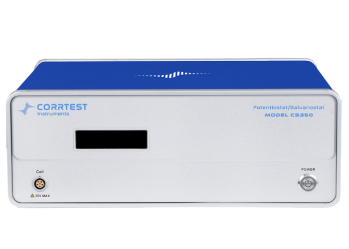
Product example: CS310M single-channel potentiostat/galvanostat with EIS (product page: CS310M, ±10 V, ±2 A, EIS to 1 MHz).
The three-tier approach maps onto the listed ranges as follows. Specifications are indicative and must be checked against the manufacturer documentation for the exact quoted model and revision, particularly where published figures conflict.
-
Teaching and budget screening: portable instruments. The portable potentiostat range includes the CS100 portable potentiostat/galvanostat without EIS, listed with a ±10 V potential control range and a published current limit that differs between distributor and CorrTest manufacturer literature. A version with EIS, the CS100E, adds a listed frequency range of 10 µHz to 1 MHz with a ±10 V potential-control range; confirm its revision-specific maximum current before ordering. For routine small-disc teaching CV, either may be suitable once the required current range, available scan rates and solution compatibility are confirmed.
-
Low-current screening: compact electrochemical station. The ECSTAT2020 electrochemical station is listed with a ±10 V potential range and current ranges from 100 pA to 10 mA (maximum ±30 mA), with potentiostat, galvanostat, bipotentiostat, ZRA and impedance operating modes and a listed frequency range of 10 µHz to 1 MHz. The low-current ranges make it suitable for smaller electrodes. MicruX specifies USB-C interfacing and EC Manager software; confirm the supplied cables, licence and operating-system requirements in the quotation.
-
Research-group workhorse: single-channel benchtop. The CS310M single-channel potentiostat/galvanostat with EIS lists a ±10 V potential range (customisable to ±12 V), ±21 V compliance voltage, a ±2 A current range with 10 programmable ranges, 1 pA current resolution, manufacturer- and configuration-dependent potential resolution, EIS from 10 µHz to 1 MHz, USB 2.0 and Windows 10/11 software. It supports two-, three- and four-electrode configurations. Confirm the exact potential-resolution conditions and pulse-technique list against the CorrTest CS310M datasheet, as published descriptions are not identical.
-
Higher current or wider EIS range. The single-channel range offers higher-current models and compatible boosters, but their maximum current, compliance and EIS frequency range must be verified for each exact instrument/booster configuration. This is the territory of electrocatalysis at large-area electrodes, rather than starter CV.
-
Two working electrodes at once, or ring-disc work. The bipotentiostat and RRDE systems category is the right place to look when you need to detect a product at a second electrode. Section 10 treats this as an advanced addition.
-
Throughput. If a whole class or a screening campaign needs to run in parallel, the multichannel range is the alternative to buying several single-channel units.
For a deeper treatment of the cell side of this decision, see the electrochemical cell selection guide.
3. 3. Electrochemical cell: volume, atmosphere and temperature control
An unexpected cathodic feature that varies between scans may arise from dissolved oxygen, but the oxygen-reduction potential depends on electrode material, pH, electrolyte and scan conditions. Compare an air-equilibrated blank with a suitably deaerated blank before attributing a wave to oxygen; neither −0.7 V nor −0.3 V versus Ag/AgCl is a universal diagnostic threshold.
A cell for CV has four jobs. It must hold three electrodes with the tip of the reference electrode close to the working electrode. For oxygen-sensitive work, it must also allow controlled deaeration and an inert-gas headspace without pressurisation. It must be chemically inert to your solution. And ideally it should let you control temperature, because diffusion coefficients and rate constants are temperature-dependent.
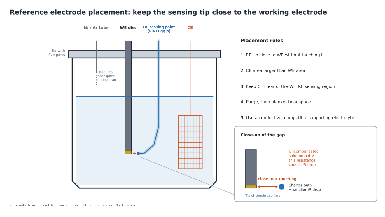
Position of the reference electrode. The uncompensated resistance between the tip of the reference electrode and the working electrode surface causes iR drop, which shifts and broadens peaks. Position the reference sensing point close to, but not touching or blocking, the working electrode. Use an adequately conductive, chemically compatible supporting electrolyte, and quantify or compensate uncompensated resistance where appropriate.
Atmosphere. When the experiment requires removal of oxygen, purge with suitable high-purity nitrogen or argon for a method- and volume-dependent period, then move the sparging tube into the headspace if a quiescent solution is required. A controlled-atmosphere cell can reduce air ingress, but gas inlet and outlet lines must remain appropriately vented: an ordinary sealed CV cell is not a pressure-rated reactor. For volatile or flammable solvents, follow the SDS, ventilation and institutional risk assessment.
Material. Borosilicate glass is the default for neutral and acidic aqueous solutions and most organic solvents. Strong alkali can attack borosilicate glass, and some fluoride-containing solutions can etch glass; a suitably specified PTFE cell may be preferable after checking all seals, electrodes and fittings. Fluoride-containing acids require a separate hazardous-chemical assessment.
Volume. A larger volume is more forgiving of small evaporation losses and electrode contamination, but uses more analyte. A small-volume cell is valuable when the analyte is expensive, as it often is in synthetic chemistry.
Product example:unsealed borosilicate glass electrochemical cell (product page: unsealed glass cell).
The electrochemical cell range lists eight formats. Available nominal volumes and usable working volumes vary by model; specify the required liquid volume, electrode immersion depth and headspace when requesting a quote.
-
Glass electrochemical cell, unsealed: borosilicate glass with a PTFE lid and gas inlet and outlet ports. The sensible budget and teaching choice.
-
Sealed electrochemical cell: screw-cap cell with provision for gas purging, for controlled-atmosphere work; keep purge outlets safely vented.
-
Small-volume conical three-electrode cell: for scarce analyte.
-
Small-volume sealed cell with titanium electrode holders: sealed tubular format with titanium T-bar clamps.
-
Jacketed sealed glass cell: double-wall glass with PTFE lid, for temperature-controlled work.
-
Five-port electrolytic cell and the jacketed five-port version: five PTFE ports for electrodes and gas lines, the flexible choice when you want a Luggin capillary, a thermometer and a gas dispersion tube in addition to the three electrodes.
-
PTFE electrochemical cell (inert reactor): all-PTFE with a sealed lid, for selected alkaline or fluoride-containing media, subject to complete material-compatibility and safety checks.
Beaker, sealed, jacketed, H-cell and flow formats are compared in the cell selection guide.
4. 4. Working electrodes: choosing material and diameter
The first voltammogram from a new glassy carbon electrode shows peaks 300 mV apart where an ideal reversible one-electron model predicts about 59 mV at 25 °C, and nobody in the group can say whether the fault lies in the electrode, the solution or the instrument. Electrode material and surface condition are possible contributors, alongside solution resistance and electron-transfer kinetics, and they are the easiest variables to control if you choose well.
Material determines the potential window and the chemistry. Glassy carbon offers a wide window in both aqueous and organic media and is relatively inert, making it a practical general-purpose choice when background measurements confirm compatibility. Platinum is useful when its surface activity towards hydrogen adsorption, oxygen evolution, or small-molecule oxidation is relevant, and its characteristic surface features in acid are a built-in cleanliness test. Gold is the substrate of choice for thiol self-assembled monolayers and for certain bio-electrochemical work.
Diameter determines current, and therefore iR drop and noise. For otherwise identical planar-disc diffusion-controlled conditions, peak current approximately scales with geometric area: a 5 mm disc can give about 2.8 times the current of a 3 mm disc. Actual iR drop also depends on electrolyte resistance and reference placement. A 3 mm disc is a convenient general-purpose laboratory size. Smaller discs of 1 or 2 mm can reduce total current and therefore iR error in a given setup and suit expensive noble-metal substrates. Larger discs are for material-limited electrocatalyst studies, where you drop-cast an ink and need enough area to measure something.
Know your area. Geometric area follows from diameter: a 3 mm disc is about 0.071 cm², a 2 mm disc about 0.031 cm². The 11.28 mm diameter in the listed glassy carbon range corresponds to almost exactly 1 cm², which simplifies reporting geometric current density (not electrochemically active surface area). Check whether the electrode's insulating shroud is exposed to your solvent. The listed disc-electrode range specifies a PTFE coating; nevertheless, confirm the complete shroud, seal and adhesive compatibility for the exact electrode and solvent before ordering.
Product example: disc working electrodes in glassy carbon, gold and platinum (product page: disc working electrodes).
-
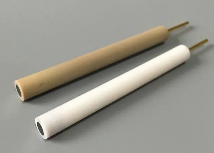
Disc working electrodes are listed in glassy carbon (1, 2, 3, 4, 5, 6, 7, 8, 9, 10, 11.28, 12, 15 and 20 mm), gold (0.5, 1, 2, 3, 4, 5 and 6 mm) and platinum (0.5, 1, 2, 3, 4, 5 and 6 mm). For a starter kit, a 3 mm glassy carbon disc is a sensible first purchase; add 2 mm platinum and 2 mm gold when your work needs them.
-
L-type working electrodes in glassy carbon and gold (2, 3 and 5 mm) are bent so that the disc faces downward, which helps in small cells and low-volume work.
-
Carbon paste electrodes (2, 3 and 5 mm) are the right choice for modified electrodes where you want to mix an active component into the paste.
-
Rod electrodes in glassy carbon and graphite (3 to 6 mm diameter, 100 mm total length with 80 mm active rod) suit immersion-style experiments.
-
Plate electrodes, including glassy carbon at 10 × 10 × 2 mm and platinum at 10 × 10 × 0.1 mm, and platinum plate sheet at 99.99% purity are for larger-area work; the plate electrode clamps hold them. The page states two different specimen thickness limits (up to 5 mm in the product cards, below 1 mm in the table), so confirm before ordering.
Diameter and a PTFE coating are listed for some disc electrodes, but exposed area, full seal construction and material grade must still be verified for the exact item. For quantitative work, request them in writing and record them in your laboratory notebook.
Polishing is half of working electrode ownership. The next sections cover the rest of the circuit before returning to it in section 8, and the guide to polishing and maintaining glassy carbon, gold and platinum electrodes covers it in depth.
5. 5. Reference electrodes: matching the electrode to your solvent and electrolyte
A reviewer asks what your potentials are measured against, and you realise that the reference electrode in the cell was a silver wire in the analyte solution, that nobody calibrated it, and that the peak you assigned has drifted by 80 mV between the first and last scan. The reference electrode is the ruler for every potential in the paper, and a ruler that changes length is not a ruler.
What a reference electrode must do. It must hold a stable, reproducible potential while passing almost no current. For conventional liquid-junction reference electrodes, this normally involves a defined redox equilibrium, a specified filling electrolyte and a suitable junction to the test solution; other designs require their own validation.
Match the electrode to the solution.
-
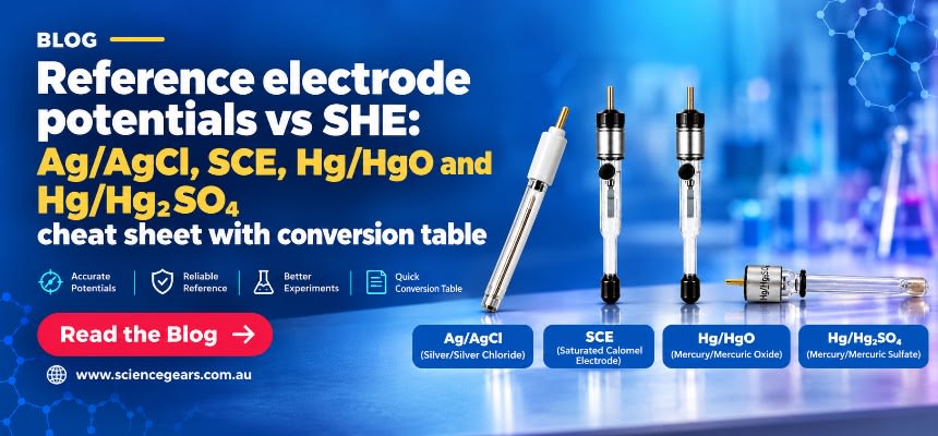
For aqueous chloride-compatible solutions, Ag/AgCl in saturated KCl is the most common choice. At 25 °C, Ag/AgCl with saturated KCl is commonly assigned approximately +0.197 V versus the standard hydrogen electrode (SHE) and is mercury-free.
-
The saturated calomel electrode (SCE, Hg/Hg₂Cl₂ in saturated KCl) is approximately +0.24 V versus SHE at 25 °C; +0.244 V is a commonly reported SCE potential, not the standard-state Hg₂Cl₂/Hg half-reaction potential (approximately +0.268 V). Record the KCl filling, temperature and manufacturer calibration before converting reference scales. SCE contains mercury and requires approved handling and waste disposal.
-
For strongly alkaline media, an Ag/AgCl electrode may introduce chloride and junction-potential errors. Hg/HgO is a commonly used alkaline reference when mercury is permitted; ScienceGears lists a 1 M KOH filling and a nominal potential near +0.098 V versus SHE at 25 °C for that configuration. Confirm the exact filling, hydroxide activity, temperature and compatibility with the test solution; use mercury-handling and waste controls.
-
For sulfate-containing acid solutions where chloride is unacceptable, Hg/Hg₂SO₄ offers a chloride-free alternative, but its potential depends on the specified sulfate-containing filling electrolyte and temperature, and it contains mercury.
-
For hydrogen evolution, oxidation and other pH-dependent reactions, the reversible hydrogen electrode (RHE) provides a pH-dependent reference scale when its equilibrium conditions are valid. Direct RHE operation uses hydrogen and requires appropriate gas controls; a calibrated conversion from a suitable reference may be used where justified.
-
For organic solvents, an aqueous reference electrode can introduce water or chloride and poorly controlled liquid-junction potentials. A compatible non-aqueous Ag/Ag⁺ electrode is a common option. IUPAC recommends the ferrocene/ferrocenium (Fc/Fc⁺) couple as a reference redox system for reporting non-aqueous potentials; use an internal standard when it does not interfere with the analyte, or a carefully validated separate-standard measurement when it does.
-
A bare silver wire is a pseudo-reference. It is acceptable for screening when you add an internal standard such as ferrocene, but must not be treated as an absolute potential scale without measured calibration against an appropriate redox standard.
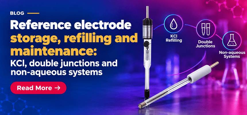
The double-junction question. A double-junction design reduces, but does not eliminate, transfer of the inner filling electrolyte into the sample. Consider it for chloride-sensitive or otherwise incompatible solutions, selecting the outer bridge electrolyte to minimise contamination and junction-potential uncertainty.
Luggin capillary. When iR drop is a problem, a Luggin capillary brings the reference electrode's sensing point close to the working electrode surface while keeping the electrode body away from the current path. Avoid contact with the working electrode and do not obstruct mass transport or place the tip in a gas-bubble path; evaluate remaining uncompensated resistance under the actual conditions.
Product example: Ag/AgCl reference electrode in saturated KCl (product page: Ag/AgCl reference electrode).
The reference electrode range lists:
-
Ag/AgCl reference electrode, listed as stable, mercury-free and approximately +0.197 V versus SHE at 25 °C with saturated KCl. The first electrode to buy.
-
Non-aqueous Ag/Ag⁺ reference electrode for organic electrochemistry. The solvent and supporting electrolyte of the filling are not stated; confirm the specified Ag⁺ concentration, solvent, supporting electrolyte and frit compatibility.
-
Silver wire pseudo reference electrode for screening with an internal standard.
-
Saturated calomel electrode and the double salt bridge saturated calomel electrode.
-
Hg/HgO reference electrode for alkaline media, listed near +0.098 V versus SHE at 25 °C for 1 M KOH filling.
-
Hg/Hg₂SO₄ reference electrode for sulfate media, with a filling-dependent reference potential; obtain the exact value for the quoted model.
-
Reversible hydrogen electrode for pH-dependent electrocatalysis.
-
J-type fritted Luggin capillary for reference placement.
Dimensions are not stated for any of the reference electrodes on the live pages. Check that the electrode body fits the port diameter of the cell you have chosen, because this is the most common mechanical mismatch in a new kit.
For a starter kit, buy one Ag/AgCl electrode and, if you work in organic solvents, one non-aqueous Ag/Ag⁺ electrode. Add others only where the chemistry and safety arrangements justify them; mercury-containing or hydrogen-based references need additional controls.
6. 6. Counter electrodes: keeping the auxiliary reaction out of your data
The cyclic voltammogram of a well-behaved redox couple is distorted at high scan rates, the baseline climbs steadily over repeated cycles, and visible changes may appear on an electrode or in solution. The counter electrode is passing the current that the working electrode demands, and whatever reaction it performs is happening in your cell.
Function. The counter electrode closes the circuit. In a three-electrode cell, the potentiostat drives whatever current is needed through the counter electrode to hold the working electrode at the setpoint relative to the reference. The counter electrode's potential is not controlled and adjusts within the instrument’s compliance-voltage limit.
Area. A counter electrode with an area comparable to or smaller than the working electrode can become the limiting electrode, forcing the potentiostat to apply large overpotentials at the counter. The widely used rule is that the counter electrode area should be larger than the working electrode area, but the exposed wetted area and allowable counter current must be checked rather than assuming every platinum wire is sufficient. For larger working electrodes, or experiments with high currents, consider mesh, gauze or another compatible high-area counter electrode.
Material. Platinum is a common choice because it is conductive and robust in many systems, but it is not chemically or electrochemically inert under every counter reaction. Two cautions apply. First, in electrocatalysis, particularly hydrogen evolution and oxygen reduction, dissolved platinum from the counter electrode can redeposit on the working electrode and give false activity. Compatible carbon counter electrodes can reduce platinum-redeposition risk but may corrode, release impurities or produce interfering species, particularly at anodic potentials. Second, products from the counter electrode can reach the working electrode. For experiments where this matters, isolate the counter compartment behind a frit or membrane, as an H-cell does.
Practical points. Place the counter electrode to provide an unobstructed current path without crowding the working electrode or reference sensing point. Keep it clean: exposure to sulfur compounds, amines or organics can deactivate platinum.
The counter electrode range lists six forms:
-
Platinum wire electrode: straight wire of about 0.5 mm diameter with customisable length. The budget and teaching choice.
-
Platinum helix wire electrode: PTFE-sheathed helix, about 0.5 mm diameter and 230 mm length, with more surface area in the same volume.
-
Platinum plate electrode: flat plate, for example 10 × 10 × 0.1 mm.
-
Platinum mesh electrode: wire diameters of 0.1 to 0.5 mm, sizes up to 30 × 30 mm, listed at about 99.9 to 99.95% purity. The most flexible all-round choice for a research group.
-
Platinum gauze electrode: cylindrical 50-mesh gauze of 23 mm diameter and 20 mm height, for high-current and large-volume work.
-
Graphite rod counter electrode: graphite core of 3 to 6 mm diameter, PTFE-sheathed with a brass connector, about 130 mm total length. A sensible low-cost option and a possible alternative when platinum contamination is a concern, provided carbon stability is verified.
Purity is stated only for the mesh electrode. For the others, ask for the platinum grade at quotation.
The guide to selecting a counter electrode covers material trade-offs and contamination diagnosis in more detail.
7. 7. Cables, shielding and mounting: where noise and drift start
A current trace at the nanoampere level carries a clean 50 Hz sinusoid on top of the signal, the baseline wanders when someone opens the laboratory door, and moving the cell lead changes the noise. These patterns often arise from leads, grounding or the laboratory environment, although instrument faults and measurement settings should also be checked.
Cables. The cell cables carry the working, sense, reference and counter connections from the instrument to the cell. The practical rules are: keep the leads short; keep the working electrode and reference leads away from mains cables and power supplies; do not coil excess lead length; and check the crocodile or pin connectors for corrosion, since a high-resistance contact in the reference lead can look like a failing electrode. For low-current work, use shielded low-noise leads supplied with the instrument and follow the exact instrument manufacturer’s shielding and grounding scheme rather than making ad hoc earth connections.
The live ScienceGears product pages do not list a separate cable category, so the cell cable set is specified together with the potentiostat. Ask at quotation which leads are included, how long they are, and whether a low-current or shielded lead set is available for your instrument.
Faraday cage. A conductive enclosure around the cell diverts external electric-field interference to ground. Whether a cage is required depends on signal-to-noise ratio, electrode impedance, cable design and local interference. It is especially useful for low-current and microelectrode measurements, but there is no universal current threshold. Connect the cage and route leads according to the potentiostat manufacturer’s recommended grounding arrangement, avoiding unsafe earth modifications and unintended ground loops. A cage is primarily effective against electric-field interference and many radio-frequency disturbances. Low-frequency magnetic interference, for example from a nearby transformer or stirrer motor, may need additional strategies such as moving the source or the cell.
Mounting. Vibration produces noise that looks electrochemical. Use a stable surface, clamp the electrodes firmly, and keep stirrer motors, pumps and heaters away from the cell.
-
The Faraday cage for electrochemical measurements is listed with a standard size of 24 × 23 × 30 cm and custom sizes on request. It is described as a conductive enclosure, either continuous metal or fine mesh, with a ground connection provision, and it accommodates beakers, H-cells, corrosion cells and microelectrode rigs. Custom cable-entry and feedthrough styles are available, and the page notes accommodation for gas purge lines, temperature probes and illumination requirements. Construction material and shielding effectiveness are not stated, so ask if you have a specification to meet.
-
For plate-shaped specimens, the electrode clamp and holder range lists platinum, gold, glassy carbon, graphite and stainless steel clamps, with custom clamping thickness on request. The specimen thickness limit is stated inconsistently on the page, so confirm it.
8. 8. Consumables: polishing, electrolyte and purge gas
The first scan on a freshly unwrapped glassy carbon electrode is sluggish and noisy, the second is a little better, and the tenth looks like the literature. The electrode surface may be changing during these scans; do not assume that cycling is a validated cleaning procedure or that it identifies the cause of an abnormal response. Treat the electrode surface as a reagent you prepare fresh for each session.
Polishing. The standard approach is a sequence from coarser to finer alumina on a flat, clean pad, with thorough rinsing between grades and a separate pad for each grade so that coarse particles are never carried to a finer stage. For routine glassy-carbon discs, a 0.05 µm alumina finish with gentle pressure and thorough rinsing is common. Use coarser grades, silica or abrasive papers only when the electrode manufacturer permits them; abrasive treatment can damage thin films, modified surfaces and some polished metal electrodes.
Electrochemical cleaning. Electrochemical conditioning may be appropriate for clean platinum or gold, but is not an automatic next step after mechanical polishing. Choose acid composition, reference scale, scan limits and cycle count from a validated method for the exact metal, surface and research objective. Aggressive positive potentials can oxidise or dissolve the metal, while repeated cycling can change the surface. Follow corrosive-acid SDS and institutional procedures; assess cleanliness by reproducible background and appropriate characteristic surface features, not a universal voltage window.
Electrolyte. The supporting electrolyte carries current and suppresses migration, so its concentration sets the solution resistance. Use analytical-grade salts and high-purity water, and prepare fresh solutions for quantitative work. For the suggested benchmark, use potassium ferrocyanide and potassium chloride, with a separate blank of supporting electrolyte; maintain the formulation consistently between tests. Follow the reagent SDS and do not acidify ferrocyanide/ferricyanide solutions. For non-aqueous work, you need dry solvent, a supporting electrolyte such as a tetraalkylammonium salt, and a suitable redox standard such as ferrocene where it does not react with or overlap the analyte. ScienceGears lists battery-focused electrolytes and salts under its battery materials range, but not general analytical reagents for CV, so source those from your usual chemical supplier.
Purge gas. When deaeration is required, use high-purity nitrogen or argon with suitable tubing and a controlled, safely vented gas flow; raise the sparging tube into the headspace during quiescent CV measurements. Gas is not supplied by ScienceGears, so arrange it locally.
The electrode polishing kit is listed as a full set containing two 100 × 100 mm glass bases, 20 g each of 1.0 µm, 0.3 µm and 0.05 µm alumina powder, five velvet polishing pads, five microcloth polishing pads, and five sheets each of 2000 and 3000 grit abrasive paper. It suits glassy carbon, platinum and gold discs. Alumina phase, glass base flatness and pad dimensions are not stated, so request them if your method requires them.
The guide to polishing and maintaining glassy carbon, gold and platinum electrodes gives the full sequence and the voltammetric checks.
9. 9. Day-one validation: proving the whole kit works
You have assembled the kit, the software shows a plausible trace, and you have no way of knowing whether the plausible trace is correct. A reproducible diagnostic run with a well-characterised redox couple helps identify wiring, surface, solution and reference problems, but does not independently certify every instrument specification. Record it as a baseline whenever a component or method changes.
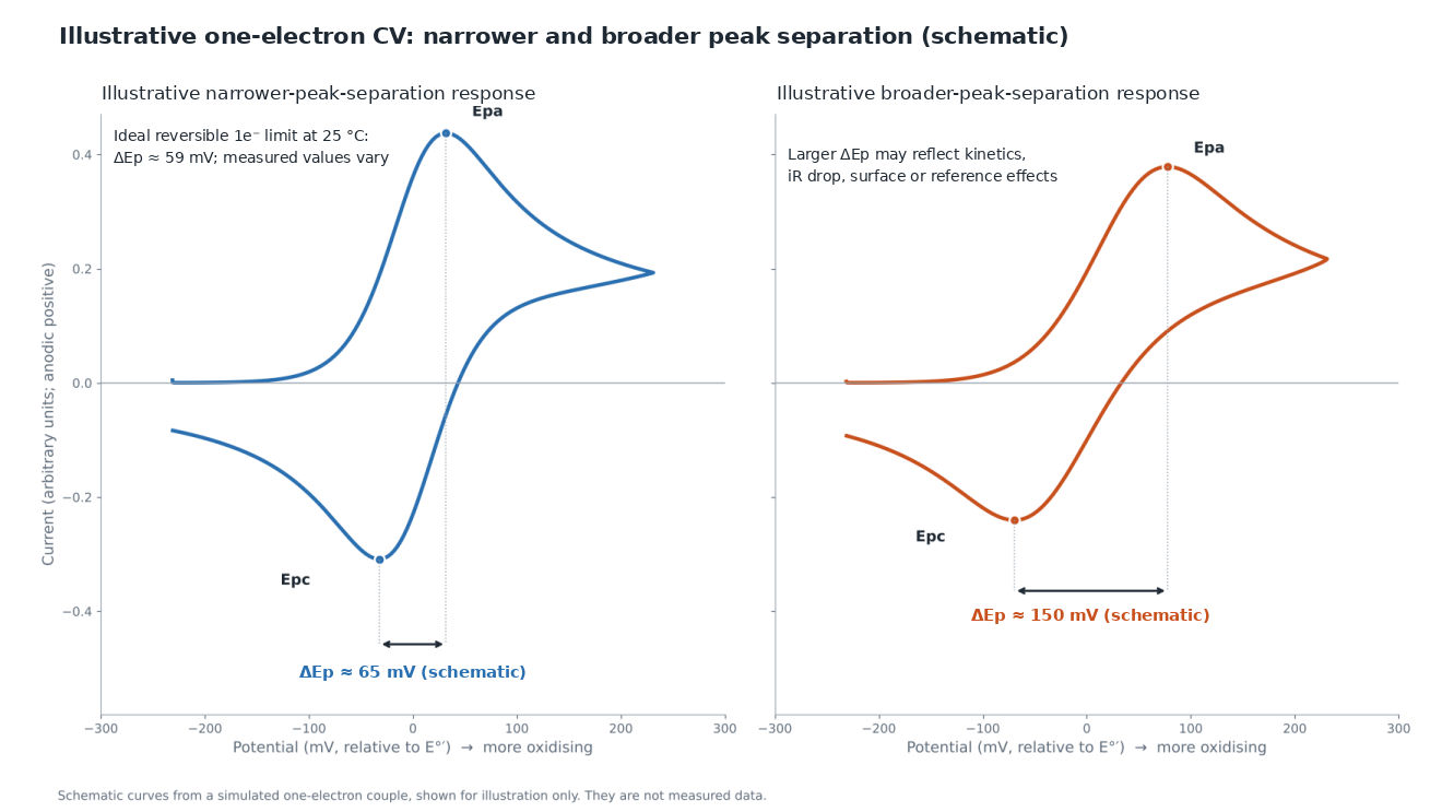
The test. Prepare 1 mM potassium ferrocyanide in 1 M KCl in high-purity water. At 100 mV/s, compare the voltammogram with the response established for your electrode preparation, electrolyte, reference and temperature. The ferri/ferrocyanide response on glassy carbon is surface- and condition-sensitive; a fixed 60–70 mV pass band is not universal. The ideal reversible one-electron peak separation at 25 °C is approximately 59 mV in the applicable planar semi-infinite-diffusion model, before kinetic and uncompensated-resistance effects. The article A practical beginner's guide to cyclic voltammetry (Elgrishi et al., J. Chem. Educ. 2018, 95, 197–206) is a useful peer-reviewed guide to interpretation, electrode preparation and experimental limitations (DOI: 10.1021/acs.jchemed.7b00361).
Procedure.
-
Polish the glassy carbon working electrode as in section 8, finishing with 0.05 µm alumina and a thorough rinse.
-
Assemble the cell with the reference tip close to the working electrode and the counter electrode positioned clear of the working–reference sensing region.
-
When oxygen exclusion is required, purge with nitrogen or argon for a validated period and maintain a safely vented inert headspace; use an electrolyte-only blank for comparison.
-
For this aqueous example, select a scan window that encloses both ferrocyanide/ferricyanide peaks without reaching competing electrode or electrolyte reactions (−0.1 to +0.6 V versus a verified Ag/AgCl reference is an indicative starting window, not a universal setting). Scan at 100 mV/s and record successive cycles and the electrolyte-only blank.
-
Measure ΔEp and baseline-corrected anodic/cathodic peak currents. A magnitude ratio near one is expected only when the reversible diffusion-controlled assumptions apply and no coupled chemistry or overlapping background distorts the peaks.
-
Repeat at 25, 50, 100, 200 and 500 mV/s. Plot peak current against the square root of scan rate. For an ideal diffusion-controlled reversible couple at fixed concentration, temperature and electrode area, background-corrected peak current is proportional to the square root of scan rate; an apparent intercept may reflect non-Faradaic background, data treatment or departures from that model.
Reading the result.
| Observation | Probable cause | First action |
|---|---|---|
| Reproducible ΔEp near the expected value for the specified redox system and electrode | Response consistent with benchmark assumptions | Record blank, reference and baseline response |
| ΔEp larger than the established benchmark, or increasing with scan rate | Uncompensated resistance, slower electron transfer, altered surface or reference error | Check reference position, electrolyte conductivity and electrode condition; measure iR |
| ΔEp large even at 25 mV/s | Potentially slow electron transfer, altered surface, reference error or background | Check blank and reference; clean only using a validated electrode procedure |
| Peak current ratio far from 1 | Coupled chemistry, oxygen, baseline treatment or unequal diffusion coefficients | Correct the background and assess oxygen, solution composition and stability |
| Peak current not linear in √v | Adsorption, coupled chemistry, convection or background effects | Inspect electrode, blank, solution and hydrodynamic conditions |
| Mains-frequency ripple on the trace | Electrical pickup, cabling or grounding issue | Use a Faraday cage, shorten leads, check grounding |
| Drifting baseline | Reference instability, concentration change or instrument drift | Check reference filling/junction, blank and connections |
Keep the traces as your baseline for diagnosing later problems.
10. 10. Three starter kit tiers: budget, standard and advanced
A purchasing officer wants a number, a principal investigator wants flexibility, and a teaching coordinator wants thirty identical benches. Each of them is buying the same eight items at different depths. The tables identify the principal components at each tier. A functioning bench additionally needs the correct instrument-specific cell cable set, holders/clamps, supporting electrolyte, cleaning/rinsing supplies, computer/software where required, and gas equipment if oxygen exclusion is necessary. Check which accessories are supplied with each instrument. Prices depend on configuration and quantity.
Tier 1: budget (teaching laboratories and first-time screening)
Aim: a reliable bench that runs ferrocyanide, ferrocene and simple analytes in compatible aqueous media; non-aqueous work requires additional solvent-compatible cell components, a suitable reference and appropriate electrolyte, and can be replicated across a class.
| Item | Specification | Product |
|---|---|---|
| Potentiostat | ±10 V, no EIS; verify maximum current for exact CS100 revision | CS100 portable potentiostat/galvanostat |
| Cell | Unsealed borosilicate glass, PTFE lid, gas ports | Glass electrochemical cell, unsealed |
| Working electrode | 3 mm glassy carbon disc | Disc working electrode |
| Reference electrode | Ag/AgCl, saturated KCl | Ag/AgCl reference electrode |
| Counter electrode | Platinum wire, about 0.5 mm | Platinum wire electrode |
| Polishing | Alumina 1.0, 0.3 and 0.05 µm with pads | Electrode polishing kit |
| Consumables from your chemical supplier | Potassium ferrocyanide, KCl, high-purity water; inert gas if required | Local supply |
Trade-offs: no impedance capability, shielding not included by default, and a single working electrode material.
Tier 2: standard (research group and industrial R&D bench)
Aim: a bench that handles aqueous and non-aqueous work, three working electrode materials, oxygen-free conditions and EIS, so that the first year of projects does not require new purchases.
| Item | Specification | Product |
|---|---|---|
| Potentiostat | ±10 V, ±2 A, EIS 10 µHz to 1 MHz, USB 2.0 | CS310M single-channel potentiostat/galvanostat with EIS |
| Cell | Sealed cell for oxygen-sensitive work, plus a five-port cell for flexibility | Sealed electrochemical cell, five-port electrolytic cell |
| Working electrodes | 3 mm glassy carbon, 2 mm platinum, 2 mm gold discs | Disc working electrodes |
| Reference electrodes | Ag/AgCl for aqueous, Ag/Ag⁺ for organic | Ag/AgCl, non-aqueous Ag/Ag⁺ |
| Counter electrodes | Platinum mesh; graphite rod where platinum contamination matters | Platinum mesh, graphite rod |
| Shielding | Standard Faraday cage, 24 × 23 × 30 cm | Faraday cage |
| Polishing | Full alumina kit | Electrode polishing kit |
Trade-offs: a single channel, so no parallel experiments, and no temperature control.
Tier 3: advanced (method development, electrocatalysis, publication-grade work)
Aim: a bench that provides options to control reference placement, temperature and counter-electrode contamination, and can run two working electrodes at once.
| Item | Specification | Product |
|---|---|---|
| Potentiostat | Bipotentiostat or suitably rated single-channel; EIS range is model-dependent | Bipotentiostats and RRDE systems, single-channel range |
| Low-current option | 100 pA to 10 mA ranges for small electrodes | ECSTAT2020 electrochemical station |
| Parallel throughput | Several channels in one instrument | Multichannel range |
| Cells | Jacketed five-port glass, jacketed sealed glass, PTFE where chemistry and seals permit | Jacketed five-port, jacketed sealed, PTFE inert reactor |
| Working electrodes | Disc set in glassy carbon, platinum and gold, plus rod or plate geometry | Rod electrodes, plate electrodes |
| Reference electrodes | Ag/AgCl, Ag/Ag⁺, RHE, Hg/HgO, with Luggin capillary | Reversible hydrogen electrode, Hg/HgO, Luggin capillary |
| Counter electrodes | Mesh and gauze in platinum, plus graphite | Platinum gauze |
| Shielding | Faraday cage with custom feedthroughs | Faraday cage |
Trade-offs: higher cost, more components to maintain, and more calibration discipline.
11. 11. Master decision matrix
Use this table to move from a laboratory application to a specific component. Every product name links to its page.
| Application | Recommended format | Specific product | Key rationale | Key constraint |
|---|---|---|---|---|
| Undergraduate teaching CV | Portable potentiostat, no EIS | CS100 | ±10 V potential range; verify quoted maximum current and teaching method | No impedance capability |
| Teaching plus basic impedance | Portable potentiostat with EIS | CS100E | Adds a listed 10 µHz to 1 MHz EIS option; verify current limit | Maximum current differs across published manufacturer/distributor specifications |
| Research group general CV and EIS | Single-channel benchtop | CS310M | ±2 A, 1 pA resolution, ±21 V compliance, EIS to 1 MHz | Single channel |
| Small electrodes, low currents | Compact station with low-current ranges | ECSTAT2020 | 100 pA to 10 mA ranges | USB-C with MicruX EC Manager; confirm supplied accessories |
| Product detection at a second electrode | Bipotentiostat or RRDE system | Bipotentiostat range | Two working electrodes under independent control | Needs a compatible cell and electrodes |
| Aqueous CV in an air-tolerant system | Unsealed glass cell | Unsealed glass cell | Simple, low cost, gas ports for purging | Weaker oxygen exclusion |
| Oxygen-sensitive or organic CV | Sealed cell | Sealed cell | Screw-cap seal with gas purging | Confirm fill volume, sealing materials and safe vent path |
| Temperature-dependent kinetics | Jacketed cell | Jacketed five-port cell | Double-wall glass with five ports | Needs a circulating bath |
| Alkaline or fluoride media | PTFE cell | PTFE inert reactor | Resists attack that etches glass | Check seals and fluoride safety |
| General organic and organometallic voltammetry | Glassy carbon disc | Disc electrode, glassy carbon | Wide potential window, relatively inert | Needs careful polishing |
| Platinum or gold surface chemistry | Noble metal disc | Disc electrode, platinum or gold | Characteristic surface features test cleanliness | Cost; conditioning is method-specific |
| Aqueous reference, mercury-free | Ag/AgCl, saturated KCl | Ag/AgCl | ≈+0.197 V vs SHE at 25 °C with saturated KCl; mercury-free | Chloride leakage into the cell |
| Organic solvent reference | Non-aqueous Ag/Ag⁺ | Ag/Ag⁺ | Avoids water and a large liquid junction | Match filling to the solvent |
| Alkaline reference | Hg/HgO | Hg/HgO | Suitable for alkaline media with specified KOH filling | Mercury waste controls; confirm filling and reference calibration |
| pH-dependent electrocatalysis | Reversible hydrogen electrode | RHE | Potential scale follows pH | Hydrogen gas controls and calibration required for direct RHE |
| Everyday counter electrode | Platinum mesh | Platinum mesh | Large area, about 99.9 to 99.95% purity | Possible platinum dissolution/redeposition; verify counter reaction |
| Platinum-sensitive electrocatalysis | Graphite rod | Graphite rod | Avoids platinum release but requires carbon-stability checks | Less stable when strongly oxidising |
| Low-current or microelectrode work | Faraday cage | Faraday cage | Diverts electric-field interference | Does not stop low-frequency magnetic noise |
| Daily electrode preparation | Polishing kit | Electrode polishing kit | Three alumina grades, pads and papers | Alumina phase not stated |
12. 12. Frequently asked questions
What is the minimum I need to run cyclic voltammetry?
A potentiostat, a cell with three ports, a working electrode, a reference electrode, a counter electrode, electrolyte and a way to polish the working electrode. Add compatible cables and holders, a suitable preparation procedure and a blank measurement. Gas purging and a Faraday cage are experiment-dependent rather than universal requirements.
Do I need EIS on my first potentiostat?
If you will only ever run voltammetry, no. If you might characterise coatings, sensors or interfacial resistance, consider it, but compare the cost and model-specific availability of future upgrades before purchasing.
Which reference electrode should I use?
Ag/AgCl in saturated KCl for most aqueous work. Hg/HgO for selected strongly alkaline solutions where mercury handling is approved, with the filling composition documented. A non-aqueous Ag/Ag⁺ electrode for organic solvents, with an internal ferrocene standard when compatible, or a validated separate-standard procedure, to report potentials versus Fc/Fc⁺. A reversible hydrogen electrode when the pH changes between experiments and you need a comparable potential scale.
Why does my counter electrode matter if I am only interested in the working electrode?
The counter electrode passes all the current the working electrode draws, so a counter electrode that is too small, fouled or reactive becomes the limiting element in the circuit. Platinum can dissolve and redeposit on the working electrode in electrocatalysis. Choose a counter electrode with area larger than the working electrode, and consider a chemically compatible carbon counter electrode or a divided cell when platinum contamination could invalidate the result; verify carbon stability under the counter reaction.
How do I know that my setup is working before I run real samples?
Run 1 mM ferrocyanide in 1 M KCl at 100 mV/s on a freshly polished glassy carbon electrode. The theoretical reversible one-electron separation is about 59 mV at 25 °C, but the measured separation is electrode- and condition-dependent. Assess cycle-to-cycle reproducibility, corrected peak-current ratio, scan-rate dependence, electrolyte blank and reference stability instead of using a rigid 60–70 mV pass/fail limit.
Do I need a Faraday cage?
Use one when the required signal-to-noise ratio cannot be achieved with sound cabling, grounding and positioning alone. It is often valuable for nanoampere-level and microelectrode work, but need is determined by the actual noise environment, not a universal current cutoff.
13. 13. Expert support — how ScienceGears works alongside your research
ScienceGears is run by electrochemists. The technical team is PhD-trained, with direct bench experience in voltammetry, electrocatalysis and electrode preparation, so a conversation about your cell and electrodes is a conversation between researchers rather than a catalogue lookup.
Pre-purchase kit review
Before you order, send the technical team your intended electrolyte, solvent, working electrode size, expected current range and the cell you plan to use. They will check that the potentiostat, cell ports, reference electrode body and electrode shroud are compatible, and flag mismatches such as a reference electrode that does not fit the port, or a shroud that is not stable in your solvent.
Acceptance-test interpretation
Send your ferrocyanide voltammograms from section 9, including the scan-rate series, and the team will help you identify whether a large peak separation comes from uncompensated resistance, a fouled surface, a reference electrode problem or interference.
Complete system supply
Australia and New Zealand supply — confirm stock and dispatch
ScienceGears supplies laboratories across Australia and New Zealand. Confirm the exact item, availability, lead time and dispatch arrangements in the written quotation; do not assume that every product is held locally or eligible for same-day dispatch.
"A voltammogram is a property of the whole bench, not of the potentiostat: choose the cell, electrodes and polishing routine with the same care as the instrument, and benchmark the system with a documented ferrocyanide control before you trust it with a sample." — ScienceGears Technical Team
14. 14. Further reading
Related ScienceGears guides
-
Electrochemical cell selection guide: beaker cell, sealed cell, jacketed cell, H-cell and flow cell
-
How to polish and maintain glassy carbon, gold and platinum electrodes
-
How to select a counter electrode: platinum wire, mesh, gauze, graphite rod and carbon cloth
-
Metal foam electrodes for electrocatalysis: thickness, pore size, pretreatment and handling
ScienceGears product pages
Related but outside the scope of this guide
These topics use some of the same components but need different hardware and a different workflow, so they are kept out of the main body:
-
Rotating disc and rotating ring-disc electrodes: RDE and RRDE electrodes
-
Microelectrodes for steady-state voltammetry: microelectrodes
-
Disposable and screen-printed sensors: disposable electrochemical sensors
-
Divided cells for separated compartments: H-cell
-
Battery coin cells and cyclers: battery test cell options
-
Corrosion testing: corrosion test electrochemical cell
-
Spectroelectrochemistry: spectroelectrochemistry