

By the end of this guide, you Will be able to take a fouled, drifting glassy carbon, gold or platinum disc electrode from an unusable state back to a mirror finish. And you'll know it's clean because a cyclic voltammogram tells you so, not because it looks shiny.
Why surface condition can dominate data quality — even when instrument settings are correct
A researcher's first instinct when a cyclic voltammogram looks wrong is to check the potentiostat: cable connections, iR compensation, scan rate, reference electrode drift. Those checks matter, but for disc working electrodes one common source of error is the working-electrode surface itself. A working electrode surface that has picked up an oxide film, an adsorbed organic layer, or a handful of scratches from the last polish will shift peak potentials, broaden peaks, raise background current, and make one day's data incomparable with the next.
This matters more than it first appears, because electrochemistry lives and dies on reproducibility. Even modest shifts in peak position or substantial changes in double-layer capacitance can affect kinetic interpretation, mechanistic assignment and reproducibility. The working electrode is also the cheapest, fastest variable to control in the entire three-electrode cell. A five-minute polish and a diagnostic scan cost far less time than chasing a phantom instrument fault.
Glassy carbon, gold and platinum behave differently once fouled, and they need slightly different polishing and verification routines. Glassy carbon is chemically robust, but its electrochemical response is sensitive to surface contamination, polishing history and surface microstructure. Gold is relatively soft and should be polished with light, controlled pressure to minimise surface damage. Platinum can form surface oxide when cycled to sufficiently positive potentials; electrochemical conditioning is commonly used to restore a reproducible surface, while mechanical polishing is generally reserved for contamination or physical surface damage. The remainder of this guide sets out one coarse-to-fine polishing sequence and shows how to adapt it, and how to check it, for each of the three materials.
It's worth being explicit about what “surface condition” actually covers, because it's more than visible scratching. Three distinct effects sit under that heading, and a good polishing routine has to address all three. The first is physical topography: scratches, pits and an uneven plane change the real or electrochemically active surface area and can trap electrolyte or reaction products in ways that distort diffusion-controlled currents. The second is chemical fouling: adsorbed organics, reaction intermediates, or a surface oxide layer that changes the electron-transfer kinetics at the interface without necessarily being visible at all. The third is polishing debris itself. Alumina particles left behind from a previous polish can behave electrochemically as an insulating or blocking layer, even though they were introduced by the very process meant to clean the surface. A robust routine has to remove all three, in the right order, and then verify that removal electrochemically rather than assuming it from appearance alone.
This is equally true whether the electrode is a stationary disc mounted in a simple three-electrode cell or a rotating disk or ring-disk tip used for kinetic and mechanistic studies. The polishing chemistry does not change with the mounting hardware, but the consequences of skipping a step do: a poorly refreshed RDE or RRDE electrode tip will carry a fouled baseline into every rotation-rate and kinetics calculation built on top of it, often without an obvious symptom until the Koutecký–Levich analysis stops making physical sense.
The coarse-to-fine polishing sequence
A common practical approach for disc electrodes is a stepwise sequence that only gets as aggressive as the fouling requires. Most routine polishing never needs the coarse steps at all.
- Assess before you abrade. Look at the electrode face under good light, ideally with a loupe or a benchtop microscope. A healthy glassy carbon, gold or platinum disc should look like a mirror, with no visible scratches, discolouration, or dull patches. If it still looks mirror-bright and the last CV was clean, a 0.05 µm alumina touch-up is usually all that's required. Reach for abrasive paper only when there's a visible film, a deep scratch, or a surface that's clearly lost its shine.
- Abrasive paper, only when needed. For deep scratches or stubborn surface contamination, a fine abrasive may be required before alumina polishing. When using the ScienceGears Electrode Polishing Kit, the supplied 2000# and 3000# abrasive papers can be used for corrective polishing before progressing to the alumina stages. Follow the electrode manufacturer's guidance before using abrasive paper. This step is corrective, not routine — overusing it removes more material than necessary and shortens the working life of the electrode.
- 1.0 µm alumina. Dispense a small amount of 1.0 µm alumina powder onto a dedicated pad, wet it to a thin paste with ultrapure or deionised water, and polish the electrode face in a figure-eight pattern while slowly rotating the electrode about its own axis. Use light, even pressure and let the abrasive do the work, not your hand. This step removes coarse scratches and re-establishes a flat plane.
- 0.3 µm alumina. Move to a second, dedicated pad and repeat the figure-eight motion with 0.3 µm alumina. This intermediate grit removes the finer scratch pattern left by the 1.0 µm step.
- 0.05 µm alumina. Finish on a third dedicated pad with 0.05 µm alumina. This is the step that gives the mirror finish researchers rely on for low-background voltammetry, and it's the only step most labs need for day-to-day electrode refreshing between measurements.
- Rinse and inspect. Rinse thoroughly (see Section 4) and inspect the surface again before mounting the electrode in the cell.
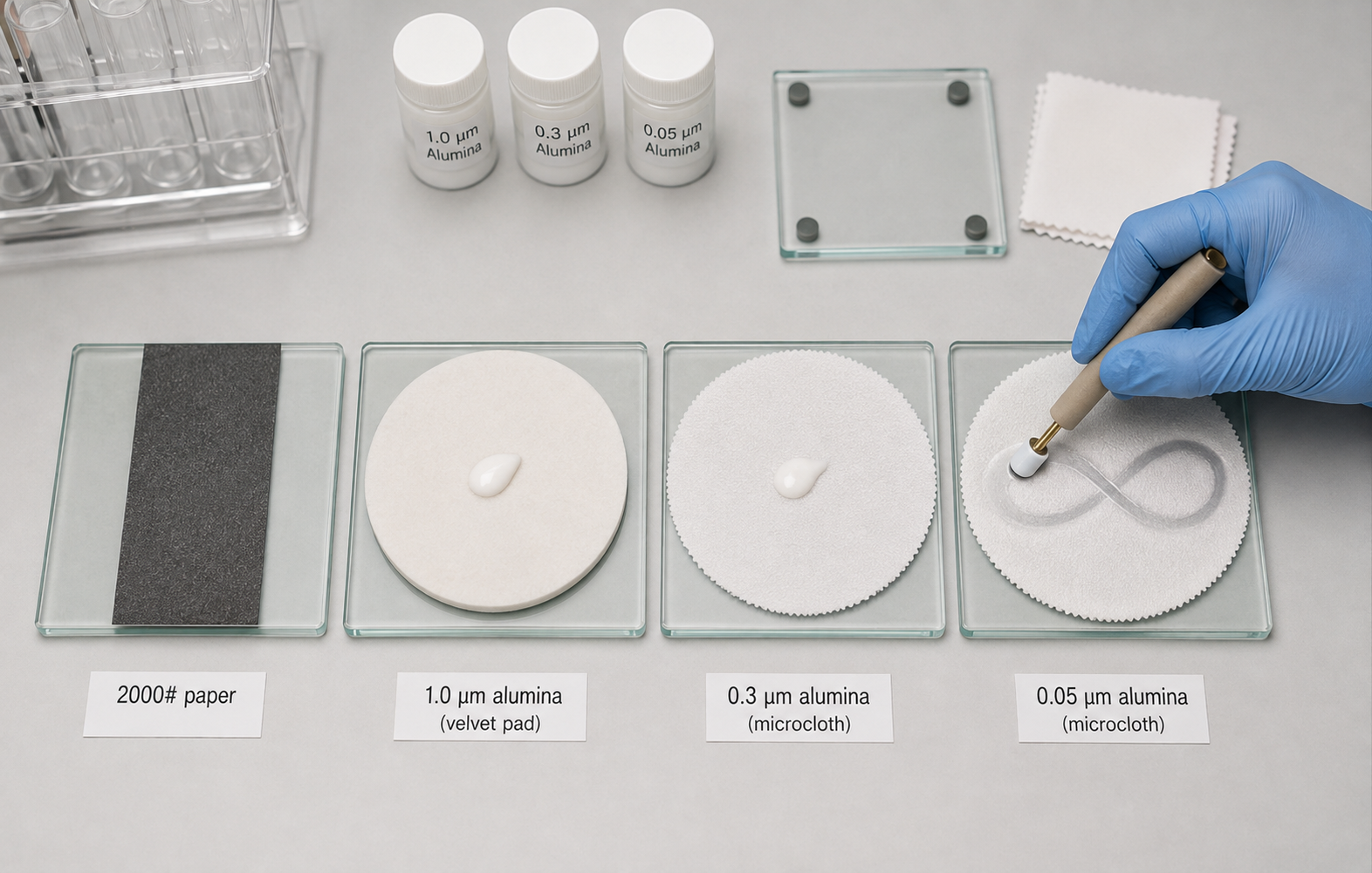
This coarse-to-fine logic is the same one built into ScienceGears' Electrode Polishing Kit, which supplies two 100 × 100 mm glass base plates, all three alumina grades (1.0 µm, 0.3 µm and 0.05 µm, 20 g each), five velvet and five microcloth pads, and five each of 2000# and 3000# abrasive papers in a single set, so the whole sequence can be run without sourcing consumables from several suppliers. It is rated for glassy carbon, platinum and gold disc electrodes, including RDE and RRDE tips.
For an overview of how polishing fits into the wider set of voltammetric methods, see ScienceGears' introduction to electrochemical techniques.
Pad selection and avoiding cross-contamination
Cross-contamination between alumina grits is a common cause of a “polished” electrode that still shows poor CV behaviour. A single stray 1.0 µm particle trapped under a 0.05 µm pad will scratch the surface on every subsequent pass, and the resulting scratch pattern is often too fine to see by eye but large enough to broaden a voltammetric peak.
Use one pad per grit, permanently
Label each pad, whether velvet or microcloth, with the alumina size it's dedicated to, and never let a coarser grit touch a finer pad. Velvet pads are typically used with the coarser 1.0 µm step, where their looser weave holds more slurry and abrades faster. Microcloth pads, with their tighter, harder weave, are generally reserved for the intermediate and final 0.3 µm and 0.05 µm steps, where a flatter, lower-relief finish is wanted. Whichever pairing your lab settles on, consistency between polishing sessions matters more than the exact pad-to-grit assignment.
Keep pads flat and clean between uses
Store pads in a covered, dust-free container, away from bench airflow that can drop particulates onto the slurry. A pad that has dried out mid-session should be re-wetted with a small amount of fresh water rather than pressed back into service dry, since a dry pad drags rather than polishes and can scratch the surface.
Retire pads before they fail you
A pad that looks glazed, has visible grooves, or has been used for many polishing sessions no longer gives a uniform finish. Extend pad life by using only a small area of the pad at a time and moving to a fresh area on the same pad with each polish, rather than wearing one spot down to the backing.
Never mix materials on the same pad set either
If your lab polishes glassy carbon and gold electrodes on the same bench, keep a separate pad set for each electrode material where practical, particularly at the 1.0 µm step. Gold is soft enough that hard particulate debris left from a previous glassy carbon polish can leave visible drag marks.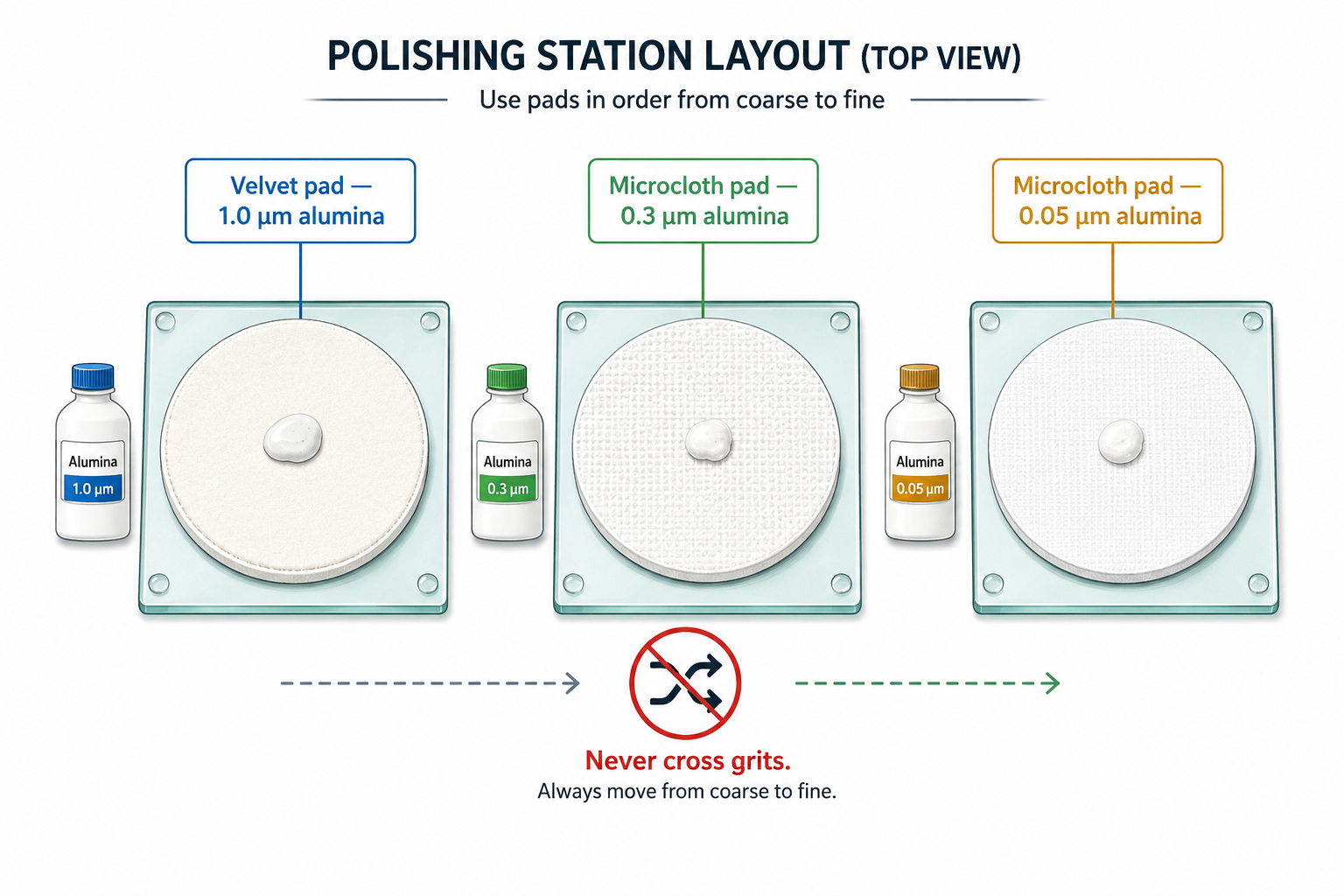
The Electrode Polishing Kit is built around this one-pad-per-grit principle: it supplies five velvet and five microcloth pads alongside the three alumina grades, so a lab running several electrode materials can maintain dedicated pad sets without constantly reordering consumables.
Rinsing, sonication and drying between steps
Polishing only removes the fouling layer; rinsing removes the polishing residue. Skip or rush this step and you reintroduce contamination at the exact moment you thought the electrode was ready.
Rinse between every grit change, not just at the end
After each alumina step, rinse the electrode tip thoroughly under a stream of ultrapure or deionised water to carry away loose alumina particles before moving to the next, finer pad. This is what stops coarse-grit particles from being dragged onto a fine-grit pad on the electrode itself.
Sonicate for a deeper clean
Routine rinsing isn't always enough, particularly after a thorough repolish, after prolonged exposure to an organic or protein-containing electrolyte, or before switching electrolyte systems entirely. In those cases, sonicate the electrode tip in ultrapure water for several minutes to dislodge alumina trapped in surface pores, then repeat in a second, fresh water bath. Residual alumina can remain in surface imperfections or on the electrode after polishing. Brief, low-power sonication in clean water can help remove residual abrasive where permitted by the electrode manufacturer; follow the manufacturer's limits for sonication time and power. Keep sonication brief and gentle for electrodes with delicate seals or embedded metal discs, since prolonged or high-power sonication can loosen the insulator-to-disc bond over repeated cycles.
Avoid organic solvents unless you know why you need them
Water is sufficient for routine alumina residue. Reach for solvent cleaning (for example, a brief rinse in ethanol or acetone) only for specific organic fouling, and always finish with a water rinse afterwards, since residual solvent can itself interfere with the double layer.
Dry with care, or don't dry at all
Many labs mount the electrode wet, straight into the cell, which avoids introducing lint or dust from a wipe. If drying is necessary, use a clean, lint-free tissue and blot rather than wipe across the disc face, since a wiping motion can redeposit particulates in a directional scratch pattern.
Check the reference and counter electrodes too
A drifting or contaminated reference electrode can mimic a poorly polished working electrode in the resulting CV. Keep a dedicated, well-maintained Ag/AgCl reference electrode on hand, refilled with fresh KCl solution and stored correctly between uses, so that a diagnostic scan is actually testing your working electrode surface and not an unrelated reference drift.
Confirming a clean surface with cyclic voltammetry
Polishing is a mechanical process; confirming it worked is an electrochemical one. A surface can look mirror-bright and still carry a thin adsorbed film invisible to the eye. Running an appropriate diagnostic cyclic voltammogram before the main experiment provides a useful electrochemical check that the electrode surface is behaving reproducibly.
Glassy carbon — the ferri/ferrocyanide probe
Ferri/ferrocyanide can be used as a surface-sensitive electrochemical check for a freshly prepared glassy carbon electrode. For an ideal reversible one-electron process at 25 °C, the theoretical peak-to-peak separation approaches 59 mV. On glassy carbon, however, the observed ΔEp can vary substantially with surface preparation, surface chemistry, electrolyte composition, concentration and scan rate. For routine quality control, compare the CV with a validated baseline obtained using the same electrode and experimental conditions rather than applying a universal ΔEp acceptance range.
Platinum — the hydrogen underpotential deposition region
For platinum, the standard diagnostic is a CV in deaerated 0.5 M H₂SO₄ over a potential window spanning the hydrogen and oxide regions. A clean polycrystalline platinum surface shows two well-resolved hydrogen adsorption/desorption peaks in the underpotential region, together with a distinct platinum-oxide reduction peak on the reverse scan. The charge associated with hydrogen underpotential deposition can be used to estimate the electrochemically active surface area. A value of approximately 210 µC/cm² is commonly used as a reference for polycrystalline platinum, but the conversion depends on surface structure, electrolyte, adsorption behaviour and background correction, so the resulting area should be treated as a method-dependent estimate. This is a useful cross-check against the electrode's geometric area from its stated diameter. Poorly resolved or “smeared” hydrogen peaks, or a suppressed oxide reduction peak, indicate the surface is still contaminated and needs another polishing cycle, sometimes followed by several potential cycles in the acid itself to complete the electrochemical clean-up.
Gold — the oxide formation/reduction couple
Gold does not show a useful hydrogen adsorption region, so the standard clean-surface check instead uses the gold oxide couple, typically run in dilute H₂SO₄. On the forward (anodic) scan, oxide formation begins in the 0.8–1.4 V region depending on the reference electrode and scan window used; on the reverse scan a single, well-defined oxide reduction peak appears, commonly reported around 0.85–0.9 V vs. a silver/silver chloride reference. Reference values such as approximately 390 µC/cm² are commonly used to estimate the electrochemically active area of polycrystalline gold from oxide-reduction charge; however, the appropriate conversion depends on the surface and experimental protocol. A broad, ill-defined, or absent reduction peak signals that the surface has not been fully refreshed.
A practical routine
In all three cases, run the diagnostic scan for several consecutive cycles rather than just one. The first cycle often “conditions” a freshly polished surface, removing the last trace of adsorbed species and settling the electrode into the electrolyte, and peak shape and position typically stabilise from the second or third cycle onward. Continue conditioning until the voltammetric profile becomes reproducible within the validated protocol. If substantial drift persists, reassess the working-electrode surface, reference electrode, electrolyte, cell cleanliness and electrical connections rather than automatically continuing to cycle or re-polish.
Cutting external noise out of the picture
A low-amplitude diagnostic peak can be masked by electrical noise long before it's masked by real chemistry, particularly in low-volume or low-concentration cells. Housing the cell in a suitable Faraday cage can reduce ambient electromagnetic interference and help separate environmental electrical noise from electrochemical causes. It does not eliminate other sources of instability such as grounding, cabling, reference-electrode drift, bubbles or poor electrical contacts. A stable electrode clamp or holder matters just as much here. A loose or shifting electrode position between polishing and mounting reintroduces exactly the kind of variability the diagnostic scan is meant to rule out.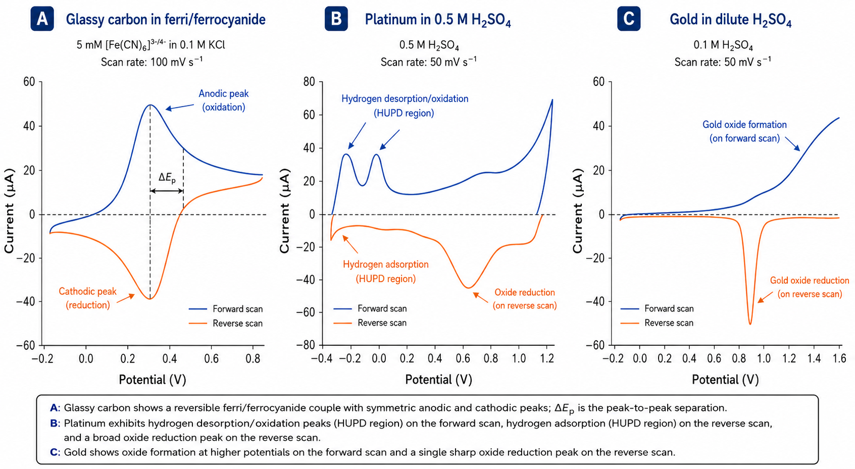
Storage and between-use maintenance
How an electrode is treated between experiments determines how much polishing it needs the next time it is used.
Routine touch-up versus thorough repolish
For day-to-day use, a brief 0.05 µm alumina touch-up before each measurement (a minute or so of light polishing followed by a rinse) is usually enough to maintain a reproducible surface, provided the electrode was in reasonable condition to begin with. Reserve the full 1.0 µm to 0.3 µm to 0.05 µm sequence for electrodes that have visibly fouled, been exposed to an aggressive electrolyte, developed scratches, or sat unused for an extended period.
Store dry and covered, or wet and appropriate to the material
Between sessions, store glassy carbon and platinum electrodes dry, capped or covered to keep dust off the disc face. This differs from reference electrodes, which typically need to stay wetted in an appropriate storage solution, so don't apply the same storage logic to a working electrode and a reference electrode interchangeably.
Protect the disc face physically
Avoid resting the electrode disc-down on a bench surface, avoid stacking electrodes together in a drawer where discs can contact each other, and use a dedicated electrode stand or rack wherever possible. Most surface scratches traced back through a lab's workflow originate from casual handling between experiments, not from the polishing process itself.
Track polishing history for shared equipment
In a multi-user lab, a simple logbook noting the date of last full repolish and any unusual CV behaviour observed can save considerable troubleshooting time. A “clean” surface reported by one user is only useful information to the next user if it's dated and specific.
Adjust the schedule for rotating and ring-disk tips
RDE and RRDE electrodes see more mechanical handling than a simple stationary disc, since they're mounted and dismounted from a rotator shaft between experiments. Inspect the collet or mounting thread each time for alumina residue, and polish the disk (and, for RRDE, the ring separately) before every mounting rather than assuming the previous session's finish has survived storage and transport intact. For RRDE designs with a removable disk, polishing the disk separately from the ring can reduce cross-contamination between electrode materials. For fixed RRDE assemblies, follow the manufacturer's polishing procedure and maintain a flat, even electrode surface. Ring–disk geometry determines theoretical collection efficiency; polishing should not materially alter that geometry.
Match maintenance intensity to the electrolyte
Electrodes cycled in aggressive electrolytes, such as strong acids at extended potential windows or electrolytes containing sulfur- or halide-containing species, tend to need more frequent thorough repolishing than electrodes run in mild, near-neutral supporting electrolytes. If a particular experiment is known to foul the surface heavily, plan for a full coarse-to-fine repolish immediately afterwards rather than waiting for the next diagnostic CV to fail.
Common mistakes that quietly ruin electrode data
Most electrode-related data problems trace back to one of the following, roughly in order of how often they show up on the bench.
- Skipping the diagnostic CV. Assuming a mirror finish means a clean surface, and going straight into the real experiment, is the single most avoidable mistake in this guide. A five-minute check saves hours of troubleshooting a dataset later.
- Cross-contaminating alumina grits. Using one pad for multiple grit sizes, even “just this once,” introduces a scratch pattern that a finer grit alone cannot polish out.
- Applying too much pressure. Heavy-handed polishing, particularly on soft gold, can embed abrasive particles into the surface rather than removing material cleanly, and can round the disc edge, changing its effective geometric area over time.
- Reusing a dried-out or glazed pad. A pad that drags instead of gliding scratches rather than polishes.
- Rinsing only at the very end. Failing to rinse between grit changes carries coarse particles forward through the entire sequence.
- Treating an oxide film like ordinary fouling. Platinum oxide, in particular, often needs a combination of mechanical polishing and electrochemical cycling (repeated CV scans through the hydrogen and oxide regions) to fully remove; polishing alone can leave a thin residual layer that only shows up as a suppressed diagnostic peak.
- Ignoring reference electrode condition when a CV looks “off.” A drifting or poorly maintained reference electrode can produce symptoms that look exactly like a dirty working electrode, sending troubleshooting down the wrong path entirely.
- Losing track of which pad belongs to which electrode material. In shared, multi-user labs this is a frequent, quiet source of contamination between glassy carbon, gold and platinum workflows.
A note on scope
This guide covers mechanical alumina polishing and standard CV-based clean-surface checks for polycrystalline glassy carbon, gold and platinum disc electrodes, which is the routine most labs need day to day. It doesn't cover single-crystal platinum faceting and flame-annealing protocols, diamond-slurry polishing systems used for some specialised metallography applications, or the surface preparation of disposable screen-printed sensors. Those all follow different, more specialised procedures and sit outside the scope of routine disc electrode maintenance.
Decision matrix: polishing and maintenance by application
Use this table to match your application to a recommended electrode material, the relevant ScienceGears product, and the polishing note that matters most for that workflow.
| Application | Recommended material | Specific product | Key rationale | Key polishing note |
|---|---|---|---|---|
| General-purpose aqueous voltammetry (CV, LSV) | Glassy carbon | Disc electrode, GC, 3 mm | Low background current, broad usability | Finish at 0.05 µm; verify with ferri/ferrocyanide ΔEp |
| Low-volume or high-resistance electrolyte studies | Glassy carbon (small diameter) | Disc electrode, GC, 1–2 mm | Smaller disc reduces total current for constrained cells | Light 0.05 µm touch-up between runs; avoid over-abrading small discs |
| Electrocatalysis screening (HER) | Platinum | Disc electrode, Pt, 3–5 mm | Strong, well-characterised electrocatalytic activity | Confirm via Hupd peaks in 0.5 M H₂SO₄; electrochemical cycling may be needed after oxide fouling |
| CO₂ reduction (CO2RR) screening | Gold | Disc electrode, Au, 3 mm | Favourable selectivity for CO2RR pathways | Verify via oxide reduction peak; avoid heavy pressure on soft gold |
| Surface functionalisation / self-assembled monolayers | Gold | Disc electrode, Au, 2–3 mm | Well-established thiol chemistry on gold | Use a reproducible surface-cleaning and polishing protocol before functionalisation; use coarse abrasives only when required. Mechanical polishing should not be described as guaranteeing a defect-free surface. |
| Rotating disk kinetic studies | Glassy carbon or platinum | RDE/RRDE electrodes | Controlled hydrodynamics for mechanistic and kinetic analysis | Polish the tip using the same sequence as a stationary disc before mounting on the rotator |
| Mechanistic / ring-disk product detection | Application-dependent ring and disk materials | RDE/RRDE electrodes | Ring and disk materials must be selected for the reaction and the species to be generated or detected; the ring should provide suitable electrochemical activity towards the target intermediate. | Polish ring and disk separately to preserve concentricity |
| Immersion / extended electrochemical profiling | Glassy carbon rod | Rod electrodes | Robust, conductive probe for flexible cell layouts | Rod geometry polishes the same way as a disc tip; rinse thoroughly given the larger contact length |
| Angled access to reduce Ohmic drop | Glassy carbon or gold | L-type working electrodes | Improved reference electrode proximity in confined cells | Same coarse-to-fine sequence; take care not to chip the angled body during polishing |
| Sensing / analytical electrochemistry with a fixed geometric area | Glassy carbon | Disc electrode, GC, 11.28 mm | 11.28 mm gives a convenient 1 cm² geometric area for current-density normalisation | An 11.28 mm circular exposed diameter corresponds to approximately 1.00 cm² geometric area. Use an electrochemical probe to assess electrode performance or electroactive behaviour, not to establish the geometric area. |
| Any routine polishing workflow across GC, Pt and Au | All three materials | Electrode Polishing Kit | Complete, stepwise coarse-to-fine system in one kit | Dedicate separate pads within the kit to each grit and, where possible, each electrode material |
Frequently asked questions
Which alumina grade should I finish with for routine cyclic voltammetry?
Most labs finish at 0.05 µm after stepping through 1.0 µm and 0.3 µm as needed. This sequence gives a smooth, reproducible surface suited to standard CV, LSV and EIS work on glassy carbon, gold and platinum discs.
Can I use the same alumina slurry and pad for glassy carbon, platinum and gold electrodes?
It is best avoided, particularly at the coarser 1.0 µm step. Gold is soft enough that hard debris carried over from a glassy carbon or platinum polish can drag and scratch the surface. Where lab space allows, keep a dedicated pad set per electrode material.
How do I know my glassy carbon electrode is properly polished, beyond looking mirror-bright?
Run a diagnostic CV in a ferricyanide or ferrocyanide solution. A peak-to-peak separation in roughly the 60–120 mV range at a moderate scan rate indicates a clean, well-behaved surface; wider or poorly defined peaks point back to residual fouling or polishing debris.
Why doesn't my platinum electrode show clean hydrogen adsorption/desorption peaks after polishing?
Platinum forms a genuine surface oxide during use that mechanical polishing alone does not always fully remove. Follow polishing with several potential cycles through the hydrogen and oxide regions in dilute H₂SO₄; this electrochemical cycling step is often what completes the clean-up that polishing starts.
How often should I re-polish a working electrode?
For routine use, a brief 0.05 µm touch-up before each measurement is generally sufficient if the electrode was in good condition to begin with. Reserve the full coarse-to-fine sequence for electrodes that show visible fouling, scratching, or a failed diagnostic CV.
Is electrochemical cycling a substitute for mechanical polishing?
No, the two address different problems. Mechanical polishing removes physical scratches, embedded contaminants and gross fouling. Electrochemical cycling removes thin oxide or adsorbed layers that reform or remain after mechanical polishing, particularly on platinum. Most reliable workflows use both, in that order.
Expert support: how ScienceGears works alongside your research
ScienceGears is led by a PhD-trained electrochemist with direct bench experience running glassy carbon, gold and platinum working electrodes across catalysis, sensing and corrosion research, and that background shapes how the technical team supports every polishing kit and electrode order that goes out the door.
Choosing the right electrode material and diameter before you order
Talk to our technical team before ordering if you're unsure which material, diameter or body geometry suits your electrolyte, cell volume or current range. Talk to our technical team →
Diagnostic troubleshooting
If a diagnostic CV won't come clean no matter how much you polish, our team can help work through whether the issue is the electrode surface, the reference electrode, cell contamination, or electrical noise, before you replace a perfectly good electrode unnecessarily.
Complete system supply
Local AU/NZ stock, same-day dispatch. ScienceGears holds core electrochemistry consumables, including polishing kits and standard disc electrodes, in local AU/NZ stock, with same-day dispatch on in-stock orders so a fouled or damaged electrode doesn't have to stall a research programme while a replacement ships from overseas.
“A clean electrode surface is the cheapest variable you control in the whole cell. Polish it, verify it with a CV, and rule it out before you chase anything more complicated.” ScienceGears Technical Team
Further reading
Get in touch
If you're setting up a new voltammetry workflow, troubleshooting a diagnostic CV that won't come clean, or simply need to reorder polishing consumables before your next run, ScienceGears' technical team is available to help.