
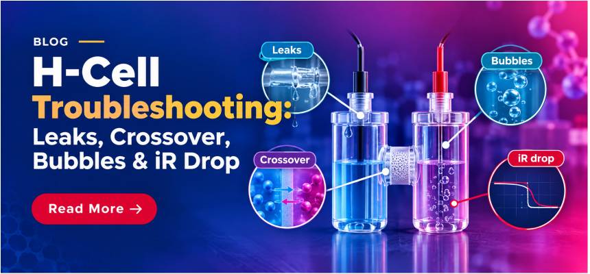
Your H-cell data has gone noisy, your faradaic efficiency does not add up, or electrolyte keeps finding its way to the wrong compartment. By the end of this guide you will be able to trace each of these symptoms back to a specific mechanical or electrochemical cause, whether it's the membrane seal, gas handling, or reference electrode geometry, and know exactly which fix, seal or accessory resolves it.
1. Why H-cells fail in predictable ways
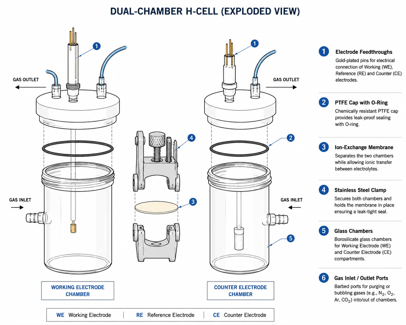
A dual-compartment cell asks a lot of a handful of seals and one thin polymer film. The working and counter electrodes sit in separate chambers, joined by a membrane that must conduct ions while blocking gas and bulk solution transfer, and the whole assembly must hold together through repeated purging, sampling and electrode swaps. When something goes wrong, whether it's a slow drip at the O-ring, a faradaic efficiency that will not close, a noisy current trace, or a potential that will not settle, the cause is almost always one of four things: a compromised seal, a membrane that is letting more through than it should, gas bubbles disturbing the electrode surface, or a reference electrode sitting in the wrong place.
Most of these failure modes share a root cause: the cell was assembled correctly for one experiment and then reused for a different chemistry, temperature or gas atmosphere without revisiting the seal, membrane or electrode geometry. This guide works through each symptom in turn, with the bench-level check that confirms the diagnosis and the fix that resolves it.
Explore the ScienceGears H-Cells & Membrane Cells range for sealed, gas-tight and membrane-separated electrochemical experiments.
2. Membrane leakage: finding and stopping electrolyte seepage
The pain point: electrolyte from one compartment is turning up in the other, the liquid level on one side is dropping faster than the other, or there is a visible film or drip at the membrane clamp after a few hours of operation.
Confirming the leak before touching the cell
Before disassembling anything, run a controlled check. Fill both compartments to the same level with the working electrolyte (not water, since surface tension and viscosity differ enough to mask a real leak), seal the cell as normal, and record the liquid level in each chamber at zero current over one to two hours with no potential applied. A measurable level change can indicate a mechanical leak, but the interpretation depends on cell geometry, membrane chemistry, electrolyte composition and possible osmotic water transport. Use the level check as a screening test, then inspect the membrane edge, clamp and seals before assigning the cause.
Where leaks actually originate
In practice, three common H-cell leak points are:
- The membrane clamp interface. If the membrane is creased, torn at the clamp edge, or simply undersized for the aperture, electrolyte bypasses the membrane entirely along its edge rather than passing through it. This is a common cause of an apparent "membrane leak," including transfer of species that the intact membrane would normally restrict.
- The O-ring or gasket seal on the electrode ports and cap. PTFE caps and glass bodies rely on O-ring compression to stay gas- and liquid-tight. A flattened, swollen (from an incompatible solvent) or dry O-ring will weep slowly rather than fail outright, which is why these leaks are often missed until a run has continued for several hours.
- Ground-glass or screw-thread joints between the two chamber halves, particularly on unsealed or lightly sealed H-cell designs, where grease has washed away or the joint has been over-tightened and chipped.
Fixing it at the bench
- Disassemble the cell and inspect the membrane against a light source; hold it up and look for pinholes, creasing at the clamp line, or a torn edge. Do not reuse a membrane that shows any of these.
- Cut a fresh membrane piece at least 5–10 mm larger than the clamp aperture on all sides so the seal lands on intact film, not on a trimmed edge.
- Hydrate the membrane in the electrolyte (or deionised water for at least 30 minutes, followed by electrolyte for another 30 minutes) before clamping. A dry membrane is stiff and prone to creasing under clamp pressure, and it will also swell after assembly, loosening a seal that looked tight when dry.
- Tighten the membrane clamp evenly and progressively (a star or cross pattern on multi-bolt clamps), checking that the membrane sits flat with no visible wrinkles.
- Inspect O-rings for flattening, cracking or chemical swelling before every reassembly, and replace rather than reuse an O-ring that has lost its round cross-section.
- Re-run the level-check protocol above before starting the real experiment.
A cell purpose-built for repeatable membrane swaps removes most of this troubleshooting at the source: the Absolutely Sealed Gas-Tight Replaceable Membrane H-Cell uses a dedicated compression membrane clamp designed for rapid, repeatable assembly, which is the detail that most reduces edge-leak failures compared with improvised clamping arrangements. For routine aqueous work where absolute gas-tightness is not the priority, the standard Sealed H-Cell offers the same O-ring and screw-cap sealing approach across capacities from 20 mL to 250 mL. If your chemistry needs a genuinely open, rapid-access format instead, for example frequent sampling where a seal is not required, the H-type Membrane Cell, unsealed, avoids the seal-maintenance question entirely by design.
3. Product crossover through the membrane
The pain point: your faradaic efficiency will not close to 100%, you are detecting anode products in the cathode compartment (or vice versa), or products generated in one compartment increasingly appear in the opposite compartment over time.
Why crossover happens even with an intact membrane
Membrane leakage (Section 2) is a mechanical failure. Crossover is different: it happens through an intact, correctly sealed membrane, because ion-exchange membranes are not perfectly selective: neutral molecules can diffuse through the hydrated polymer, while co-ion and product-species transport can occur depending on membrane chemistry, concentration and operating conditions. Two mechanisms dominate:
- Diffusive gas crossover. Dissolved H₂, O₂ and CO₂ all have measurable solubility and diffusivity within hydrated ion-exchange membranes, so a concentration gradient between compartments drives a steady flux across the film even with zero net ionic current. Thinner membranes and higher operating current densities (which increase local gas supersaturation at the electrode) both increase this flux.
- Electro-osmotic drag and co-ion leakage. Proton-exchange membranes such as Nafion carry a fixed negative charge and are designed to reject anions, but at high salt concentrations or with poorly matched electrolytes, some co-ion transport still occurs, carrying product species across with it.
Diagnosing which mechanism is dominant
Run the cell at open circuit with both compartments filled with the actual reaction electrolytes (one saturated with the anode product gas, the other clean) and monitor the clean side for contamination over time with no current flowing. Any signal here is diffusive crossover, independent of current. Then repeat under load at your working current density; a large increase in crossover rate under load points to current-driven or supersaturation-driven transport rather than pure diffusion.
Matching the membrane to the chemistry
The fix for a genuine crossover problem is almost always a membrane change, not a seal change:
- Proton-exchange membranes (Nafion). Nafion 117 (183 µm) and Nafion 115 (127 µm) offer lower gas permeation than the thinner 25–51 µm grades because permeation flux scales inversely with membrane thickness for a given concentration gradient, at the cost of higher ohmic resistance. If your priority is minimising H₂/O₂ crossover in a water-splitting half-cell study, start with the thicker grade and only move to Nafion 211 or Nafion 212 if resistance becomes limiting and some crossover is tolerable for your analysis.
- CO₂ reduction and alkaline chemistries. An anion-exchange membrane from the Fumasep FAA-3/FAB series can support transport of anionic charge carriers such as OH⁻, HCO₃⁻ or CO₃²⁻, depending on the electrolyte and operating conditions. Membrane selection for CO₂ reduction should consider ionic conductivity, product-ion crossover, cation crossover, water transport and chemical stability rather than assuming that an AEM will inherently minimise gaseous-product crossover.
- Cation-selective separation. Where the requirement is blocking anion or product crossover in redox-flow or electrodialysis-style set-ups, the Fumasep FKS/FKB cation-exchange series is designed for that transport direction.
- pH-gradient work. If your protocol deliberately maintains different pH values in each compartment, a Fumasep FBM-PK bipolar membrane splits water internally at the junction to sustain the gradient rather than letting it collapse through co-ion leakage.
For membrane selection, explore the ScienceGears Nafion and Ion-Exchange Membranes range.
Membrane conditioning can significantly affect reproducibility and should follow the requirements of the specific membrane grade and application. For Nafion, one widely used laboratory conditioning sequence is: boil in 3% H₂O₂ for one hour to remove organic residue, rinse and boil in deionised water for one hour, boil in 0.5–1 M H₂SO₄ for one hour to fully protonate the sulfonic acid groups, then rinse and boil again in deionised water for one hour, storing the membrane hydrated until use. Where conversion to the H⁺ form is required, incomplete ion exchange can affect conductivity and transport behaviour. The magnitude of this effect depends on the membrane's as-received ionic form and conditioning history.
4. Gas bubbles: noisy data and fouled electrodes
The pain point: current or voltage traces show sudden spikes and drops, cyclic voltammograms are not reproducible between cycles, or apparent overpotential creeps upward during a long constant-current hold even though nothing else has changed.
The mechanism: bubbles are insulators
Gas bubbles at an electrode do not provide the ionic conduction pathway of the surrounding electrolyte and can mask part of the electrochemically active surface or alter local current paths. A bubble adhering to or passing near the electrode blocks part of the active area and displaces conductive electrolyte from the current path, which increases both the ohmic resistance of the cell and the effective (uncompensated) overpotential at the moment the bubble is present. As bubbles nucleate, grow and detach, this resistance rises and falls in a way that shows up directly as noise or drift in current and voltage measurements, and the effect becomes more pronounced as current density increases and bubble coverage grows.
Practical fixes, from least to most invasive
- Reposition the sparge or purge line. If you are purging with N₂ or Ar for deaeration, route the gas line so the bubble stream does not pass across the working electrode face; a common mistake is placing the sparge tube directly above or beside the WE, where rising bubbles wash across the electrode on their way to the surface. Move the sparge port to the counter electrode side or to a corner of the compartment away from the working electrode, and switch to a gentle blanket purge (gas over the headspace, not through the solution) once initial deaeration is complete.
- Reduce bubble residence time at high current density. At higher current densities, gas evolution outpaces natural buoyant removal and bubbles coalesce on the electrode surface. Where your protocol allows it, mild stirring or a rotating/vibrating electrode configuration removes bubbles faster than buoyancy alone; where the protocol requires a static electrode, keep runs at high current density as short as practical and prioritise reducing bubble formation or residence at the electrode. If averaging or digital filtering is subsequently used, retain the raw data and report the processing method.
- Check electrode orientation. A horizontal, upward-facing working electrode traps rising bubbles against its own surface far more than a vertical electrode, where bubbles slide off along the surface as they grow. Where your cell geometry allows it, mounting the working electrode vertically is one of the simplest changes that reduces bubble-related noise.
- Separate gas-tight operation from open sampling. If your protocol needs a controlled, air-free atmosphere for quantitative gas product analysis, an open or lightly sealed cell will both let air in and let evolved gas escape uncontrolled, compounding the bubble problem with an air-ingress problem. A Sealed H-Cell or the Absolutely Sealed Gas-Tight Replaceable Membrane H-Cell with dedicated gas inlet/outlet and headspace-sampling ports lets you route purge and product gas separately from the electrode chamber geometry, rather than sharing one port for both jobs.
- For rapid open-access screening where sealing is not the priority, the PTFE H-Type Membrane Electrolytic Cell offers multiple ports so a dedicated purge line can be kept physically separate from the working electrode port.
5. Reference electrode placement and iR drop
The pain point: the measured onset potential for your reaction shifts with current density in a way that does not match literature, replicate runs at different currents give inconsistent Tafel slopes, or your potentiostat's compensated-resistance value seems implausibly high or keeps changing between runs.
The physics in one paragraph
In a three-electrode set-up, the reference electrode is meant to report the true potential at the working electrode surface. Between the reference electrode's sensing point and the working electrode, however, there is always some thickness of electrolyte, and passing current through that electrolyte creates a voltage drop (iR, or ohmic drop) proportional to the current and the solution resistance between the two points. If the reference electrode sits too far from the working electrode, this iR drop is added directly to your measured potential, distorting kinetic data, most visibly as a Tafel slope or onset potential that shifts with current.
The Luggin capillary trade-off
The standard fix is a Luggin capillary: a narrow glass or PTFE tube that brings the reference electrode's ionic sensing point close to the working electrode surface without placing the bulkier reference electrode body in the current path. But moving the capillary tip closer is not free. If the tip sits too close to the working electrode, it physically shields part of the electrode surface from the current, distorting the local current distribution and creating a different measurement artefact.
A practical starting approach is to position the Luggin tip close to the working electrode while avoiding disturbance of the local current distribution. A distance on the order of one to two tip outer diameters can be used as an initial guide, but there is no universal optimum: electrode geometry, electrolyte conductivity and capillary dimensions all matter. Confirm the final position from the measured uncompensated resistance and measurement stability. Increasing the distance does not create the same shielding effect, but it generally increases the uncompensated solution resistance between the sensing point and working electrode.
Bench checklist for reference electrode placement
- Measure your capillary tip's outer diameter before positioning it, and use approximately one to two tip diameters as an initial positioning range, then confirm the position experimentally. For a typical 0.5–1 mm tip, that is a working distance of about 1–2 mm from the working electrode surface.
- Keep the capillary filled with electrolyte and free of trapped air bubbles along its length; a bubble anywhere in the capillary breaks the ionic path exactly as effectively as an air gap would, and reads as an erratic or drifting reference signal rather than an obvious open circuit.
- Fix the capillary and reference electrode position mechanically (via a clamp or holder) rather than by hand, since even small day-to-day variations in tip position change the uncompensated resistance and make replicate measurements harder to compare.
- For gas-evolving working electrodes specifically, keep the capillary tip clear of the bubble stream described in Section 4. A bubble passing across the capillary opening interrupts the reference sensing path in the same way it disturbs the working electrode, and the two problems often appear together on the same trace.
- Where the impedance spectrum provides a clear high-frequency intercept, an open-circuit EIS measurement can be used to estimate the uncompensated resistance before the main experiment.
H-cell measurements, including EIS and uncompensated-resistance evaluation, can be performed using a suitable ScienceGears Potentiostat / Galvanostat with EIS.
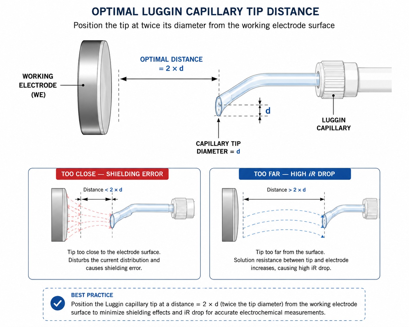
A J-Type Fritted Luggin Capillary is designed specifically for this positioning task: the fritted tip provides controlled ionic contact while the J-type geometry lets you bring the sensing point close to the working electrode while the reference electrode body itself stays clear of the compartment. It is compatible with the common reference electrode chemistries used in H-cells. See Section 6 for choosing between them.
For controlled reference-electrode positioning, see the ScienceGears J-Type Fritted Luggin Capillary.
Choosing the reference electrode chemistry itself
Placement solves the geometry problem; chemistry compatibility is separate. A quick guide:
- General aqueous work: Ag/AgCl is a common, mercury-free reference for aqueous electrochemistry when its chloride-containing filling solution and junction chemistry are compatible with the experiment.
- Chloride-sensitive samples: a double salt bridge saturated calomel electrode adds an intermediate salt bridge that limits KCl leakage into the sample, at the cost of a second junction potential to account for.
- Strongly alkaline electrolytes: Hg/HgO is the standard choice for alkaline fuel cell and battery work, where an Ag/AgCl electrode's chloride chemistry is a poor match.
- Non-aqueous or organic electrolytes: a non-aqueous Ag/Ag⁺ reference electrode avoids introducing water into a moisture-sensitive compartment, but should be calibrated against an internal standard such as ferrocene each session, since its absolute potential depends on solvent and supporting electrolyte.
- pH-independent hydrogen kinetics: a reversible hydrogen electrode is the natural reference for HER/OER studies across a pH range, though it requires a dedicated high-purity H₂ supply and gas-tight fittings.
Explore the ScienceGears Reference Electrodes range for aqueous, alkaline and non-aqueous electrochemical applications.
6. Sealing, cleaning and preventive maintenance checklist
Most of the failures above are easier to prevent than to diagnose mid-run. Build the following checks into your standard H-cell set-up routine.
Before every assembly
- Inspect all O-rings for flattening, cracking, or swelling from solvent exposure; replace rather than reuse questionable O-rings.
- Check the membrane for pinholes, creasing at the clamp line, or discolouration, holding it up to a light source.
- Confirm the membrane has been hydrated in the working electrolyte for at least 30 minutes before clamping.
- Check that ground-glass or screw-thread joints are clean and free of dried salt crystals, which can chip glass or prevent a proper seal.
During assembly
- Tighten membrane clamps evenly, in a star or cross pattern for multi-bolt designs, checking for visible wrinkles once tightened.
- Fill both compartments to matched levels before applying any potential, and note the fill levels for the leak-check protocol in Section 2.
- Position the reference electrode and Luggin capillary using the 2× tip-diameter rule from Section 5, and fix the position mechanically.
- Route purge and sparge lines away from both the working electrode and the reference electrode capillary tip.
After every run
- Rinse all glassware and PTFE components with deionised water immediately, before residual electrolyte can dry and deposit salt in seals or frits.
- Store membranes hydrated (in deionised water or a dilute electrolyte, per the membrane manufacturer's guidance) rather than allowing them to dry out and become brittle.
- Inspect frits on reference electrodes and Luggin capillaries for clogging or discolouration; clean with dilute electrolyte solution as needed rather than waiting for a visible drift problem.
- Log any seal, O-ring or membrane replacement against the cell, so recurring leaks at the same point are caught as a pattern rather than treated as one-off events each time.
Periodic checks (weekly to monthly, depending on run frequency)
- Run the open-circuit level-check protocol from Section 2 on cells in regular use, even without a specific leak complaint.
- Re-verify reference electrode potentials against a known standard, particularly when reference-electrode stability is critical or the electrode has been stored for an extended period.
- Replace O-rings on a fixed schedule for cells used with aggressive solvents or at elevated temperature, rather than waiting for visible failure.
7. Decision matrix: matching the fix to the failure mode
| Application / symptom | Recommended fix | Specific product | Key rationale | Key constraint |
|---|---|---|---|---|
| Electrolyte weeping at membrane clamp edge | Replaceable membrane cell with compression clamp | Absolutely Sealed Gas-Tight Replaceable Membrane H-Cell | Purpose-built compression clamp supports repeatable membrane alignment and sealing. | Membrane must still be cut oversized and hydrated before clamping |
| Slow evaporation/drip at O-ring seal over long runs | Screw-cap gas-tight sealed cell | Sealed H-Cell | O-ring and screw-cap design limits gas exchange and evaporation | O-rings need periodic inspection and replacement |
| Frequent sampling, seal not critical | Open-access unsealed cell | H-type Membrane Cell, unsealed | Removes seal maintenance from the workflow entirely | Not suitable where air ingress or evaporation must be controlled |
| H₂/O₂ crossover in water-splitting half-cell studies | Thicker Nafion PEM | Nafion 117 Proton Exchange Membrane | Lower gas permeation than thinner grades at a given concentration gradient | Higher membrane thickness increases ohmic resistance |
| Fast CV screening where minor crossover is tolerable | Thin Nafion PEM | Nafion 211 Proton Exchange Membrane | Lower membrane resistance reduces the membrane-related ohmic contribution during screening measurements. | More prone to pinhole failure under mechanical stress |
| CO₂ reduction with product crossover to the anode | Anion-exchange membrane | Fumasep FAA-3/FAB Series | Supports anion transport in compatible alkaline or neutral systems; crossover depends on the membrane, transported species and operating conditions. | Condition according to the manufacturer instructions for the specific membrane grade. |
| Cation-selective separation (redox-flow, electrodialysis) | Cation-exchange membrane | Fumasep FKS/FKB Series | Provides cation-selective transport; suitability depends on the electrolyte and the species that must be retained or transported. | Not a drop-in replacement for chemistries needing anion transport |
| Deliberate pH-gradient two-compartment process | Bipolar membrane | Fumasep FBM-PK Bipolar Membrane | Internal water-splitting sustains the pH gradient across chambers | Adds voltage penalty compared with single ion-exchange membranes |
| Noisy current/voltage traces from bubble interference | Multi-port cell with separated purge line | PTFE H-Type Membrane Electrolytic Cell | Extra ports keep the purge line physically clear of the working electrode | Correct port routing is still a manual set-up step |
| Quantitative faradaic-efficiency measurements requiring controlled, minimised air ingress. | Valved gas-tight cell with headspace sampling | Absolutely Sealed Gas-Tight Replaceable Membrane H-Cell | Dedicated valve/gas ports separate purge, feed and sampling from the electrode chamber | Slower to set up than an open cell |
| Reference electrode too far from working electrode, high iR drop | Luggin capillary retrofit | J-Type Fritted Luggin Capillary | Brings the reference sensing point to roughly twice the tip diameter from the WE | Must stay bubble-free and correctly positioned to avoid shielding error |
| Reference potential drift from a clogged or salt-starved frit | Refillable Ag/AgCl electrode | Ag/AgCl Reference Electrode | Refillable body allows frit cleaning and KCl replenishment | Needs periodic saturation and frit checks |
| Chloride-sensitive sample requiring reference isolation | Double-junction reference electrode | Double Salt Bridge Saturated Calomel Electrode | Intermediate salt bridge limits KCl leakage into the sample | Adds a second junction potential to the measurement |
| Strongly alkaline electrolyte reference compatibility | Hg/HgO reference electrode | Hg/HgO Reference Electrode | Stable in high-pH systems where Ag/AgCl chemistry is a poor match | Mercury handling and disposal protocol required |
| Non-aqueous or organic electrolyte reference compatibility | Non-aqueous Ag/Ag⁺ reference electrode | Non-aqueous Ag/Ag⁺ Reference Electrode | Matches the solvent system without introducing water | Requires calibration against an internal standard such as ferrocene each session |
| Loose or intermittent electrode contact during long runs | Dedicated electrode clamp/holder | Platinum Electrode Clamp / Holder | Maintains consistent contact pressure over extended runs | Rated for plate specimens under 1 mm thickness |
| Jacket seal weeping under temperature-controlled operation | Jacketed H-cell with matched fittings | Jacketed H-Type Membrane Cell | Thermal jacket enables temperature control; seal and fitting compatibility must still be verified for the operating temperature and electrolyte. | Needs recirculating bath tubing matched to the fitting size |
| Photoelectrochemical study with a leaking optical window seal | Sealed jacketed PEC cell | H type Sealed Jacketed Photoelectrochemical Cell | Purpose-built quartz window seal for gas-tight optical access | Requires careful cleaning to avoid scratching the quartz window |
| Process requiring a third isolated reaction environment | Three-chamber H-cell | Three-Chamber H-Cell (Triple H-Cell) | Extra compartment isolates a third electrolyte or reaction stage | More seals and clamps to maintain, so more potential leak points |
8. Frequently asked questions
1. How do I tell a membrane leak apart from normal gas crossover?
Run the cell at open circuit (no current applied) with both compartments filled with the real electrolytes and monitor liquid level and contamination over one to two hours. A measurable level change or fast contamination at open circuit points to a mechanical seal or membrane-edge leak; contamination that only appears once current is flowing, and grows with current density, points to diffusive or current-driven crossover through an intact membrane instead.
2. What is the correct distance for a Luggin capillary from the working electrode?
As a starting point, use roughly twice the outer diameter of the capillary tip. Closer than that risks shielding part of the electrode surface and distorting the current distribution; further away increases the uncompensated ohmic drop in your measurement. Fine-tune from that starting point using an open-circuit impedance measurement to check the high-frequency resistance.
3. Why does my faradaic efficiency not add up to 100%?
The two most common causes are product crossover through the membrane (Section 3) and gas escaping through a seal before it can be captured for analysis (Section 2). Run the open-circuit leak check first, since it rules out the mechanical cause quickly; if the cell passes that check, move to the current-dependent crossover diagnostic in Section 3.
4. Can I reuse a Nafion membrane after it has dried out?
A dried membrane can usually be rehydrated, but expect a period of instability in conductivity and permeability immediately afterwards, and inspect it closely for creasing or embrittlement cracks before reuse. For quantitative crossover or faradaic efficiency measurements, starting from a freshly conditioned membrane each time removes this variable from your data.
5. How do I stop gas bubbles from disturbing my working electrode during a long constant-current hold?
Reposition the purge or sparge line away from the working electrode face, consider a vertical rather than horizontal electrode orientation so bubbles slide off rather than accumulate, and where the protocol allows it, use mild stirring to shorten bubble residence time at the electrode surface.
6. Do I need a sealed H-cell if I am not measuring gas products quantitatively?
Not necessarily. If your work does not depend on precise faradaic efficiency or an air-free atmosphere, an unsealed or lightly sealed cell is simpler to use and maintain. Move to a gas-tight design once your protocol specifically requires controlled headspace, quantitative gas sampling, or protection from oxygen or moisture ingress.
9. Expert support: how ScienceGears works alongside your research
Our technical team is led by PhD-trained electrochemists with direct bench experience running H-cell experiments across CO₂ reduction, HER/OER benchmarking, membrane characterisation and corrosion research, so the guidance you get is grounded in what actually happens at the clamp and the capillary, not just a specification sheet.
Before you order
If you are not sure which membrane chemistry, seal format or reference electrode suits your specific electrolyte and current density range, our technical team will work through the chemistry with you before you commit to a configuration.
Talk to our technical team →
Leak and crossover diagnosis
Send us your symptom, whether it's a level change, a crossover percentage or a noisy trace, and we can help you narrow down whether the cause is mechanical, chemical or electrode geometry before you start swapping components at random.
Complete system supply
- H-Cell (all formats)
- Ion-exchange membranes (Nafion and Fumasep)
- Reference electrodes
- J-Type Fritted Luggin Capillary
- Electrode clamp/holder
- Other electrochemistry accessories
Local AU/NZ stock: same-day dispatch
ScienceGears holds local stock of common H-cell formats, membrane grades and reference electrode chemistries across Australia and New Zealand, so a failed O-ring or a depleted membrane does not have to put your project on hold waiting for an overseas shipment.
“Most H-cell problems are not exotic electrochemistry. They are a seal, a membrane edge, a bubble path or a capillary position that was set once and never revisited.” ScienceGears Technical Team
10. Further reading
- Membrane selection guide: fuel cells vs electrolysers vs H-cells
- Complete Nafion membrane specifications: thickness, properties and pre-treatment
- Cation vs anion exchange vs bipolar membranes: a complete ion-exchange membrane guide
- How to build, test and optimise a membrane electrode assembly (MEA)
- ASTM electrochemical corrosion test methods: the complete guide for your lab
- Reference electrodes for precise electrochemical control
11. Get in touch
If your H-cell setup needs a second opinion on membrane choice, sealing hardware, reference electrode geometry, or all three, our technical team is available to talk through your specific electrolyte, current density range and analytical requirements.