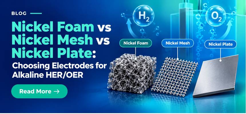


By the end of this guide, you will be able to choose a metal foam substrate by chemistry, thickness and pore size for your specific reaction, run a pretreatment protocol that actually removes contamination without over-oxidising the surface, and mount and cut the foam so your geometric area stays reproducible from one experiment to the next.
Table of contents
1. Why the substrate you build on matters as much as the catalyst
2. Anatomy of a metal foam electrode
3. Matching metal chemistry to your reaction
4. Thickness: loading capacity, ECSA and bubble transport
5. Pore size: the electrochemical surface area and mass transport trade-off
6. Pretreatment: degreasing, oxide removal and activation
7. Cutting, mounting and defining a reproducible geometric area
8. Common pitfalls and how to catch them early
9. Decision matrix: choosing your foam
11. Expert support: how ScienceGears works alongside your research
1. Why the substrate you build on matters as much as the catalyst
You have spent weeks optimising a catalyst, maybe a nanostructured hydroxide, a phosphide, or an oxide-derived film, and the cyclic voltammogram finally looks right. Then you swap from a flat nickel foil to a nickel foam of a different pore grade and the overpotential shifts by tens of millivolts, or the mass loading you thought was fixed turns out to vary two-fold between "identical" samples. Nothing about the catalyst chemistry changed. The substrate did.
This is a common failure mode in electrocatalysis research: substrate architecture is treated as a fixed, interchangeable backdrop, when in reality thickness, pore size and surface state each independently shape the current density, gas-bubble behaviour and reproducibility you measure. A catalyst that looks excellent on one foam grade can look mediocre on another, not because the catalyst changed, but because the pore network handled mass transport and bubble release differently underneath it.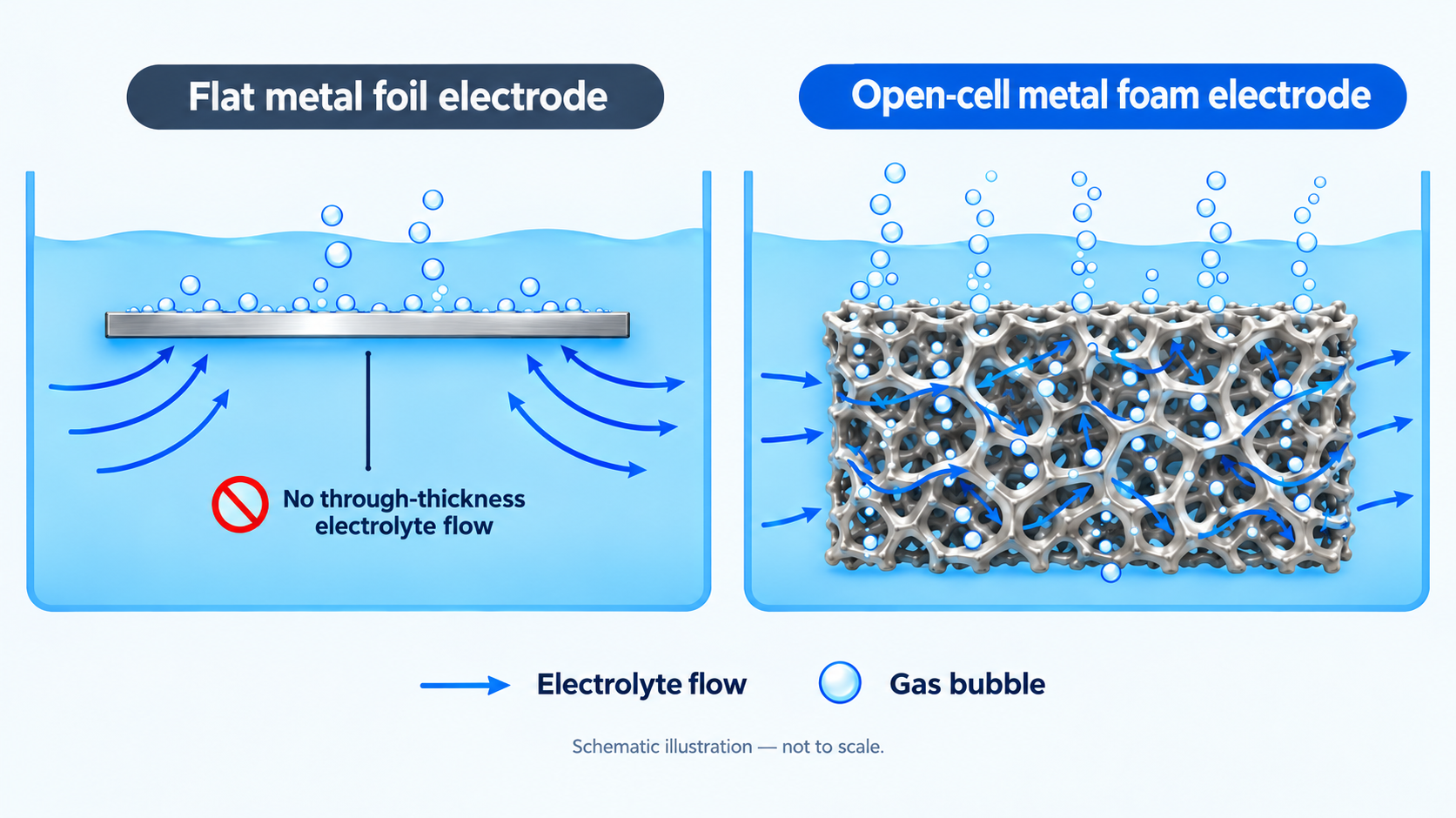
This guide sets out the practical decisions that determine whether a metal foam electrode gives you clean, reproducible electrocatalysis data: which metal to start from, how thickness and pore size trade off against each other, how to pretreat the foam without accidentally growing more oxide than you remove, and how to cut and mount it so your geometric area does not drift between runs.
2. Anatomy of a metal foam electrode
A metal foam electrode is an open-cell, three-dimensional porous metal scaffold. Unlike a closed-cell foam (think of a sealed bubble structure), an open-cell foam has pores that connect through to their neighbours, so electrolyte and gas can move through the entire thickness of the material rather than only across its outer face. That through-thickness permeability, combined with continuous metallic conduction along the ligament network, is what makes foams attractive as catalyst supports and current collectors: they offer a large effective surface area without the need for complex microfabrication.
Many commercial nickel foams are manufactured by depositing nickel onto a sacrificial open-cell polymer template, commonly polyurethane, followed by thermal treatment to remove the template and consolidate the metallic network. Manufacturing routes vary across metals and suppliers. The result is a porosity that can range widely, with nickel foam commonly reported in the 70 to 98% range by volume, depending on grade.
A few terms recur throughout foam datasheets and are worth defining precisely before you order anything:
-
Porosity: the fraction of the foam's total volume that is void space rather than metal. A foam quoted at 90% porosity is, by volume, nine parts air (electrolyte, once wetted) to one part metal.
-
Pore size or aperture means the characteristic dimension of an individual pore opening, usually quoted in micrometres or millimetres. This is the specification that most directly governs bubble transport and electrochemically accessible surface area, covered in detail in Section 5.
-
PPI (pores per inch) is a coarser, count-based descriptor of pore density along a linear inch of foam, often quoted alongside or instead of a micrometre aperture. Fine-pore foams sit at higher PPI values; coarse, high-permeability foams sit at lower PPI values.
-
Bulk density is the mass per unit volume of the foam as supplied, which scales with both the parent metal's density and the porosity. This matters when you are trying to normalise catalyst loading by substrate mass rather than by geometric area.
-
Open-cell (through-hole) rate is the fraction of pores that are genuinely interconnected rather than closed off. A foam with a through-hole rate quoted at 98% or higher is close to fully permeable; a lower figure indicates a meaningful fraction of dead-end or isolated pores that will not contribute to mass transport.
These parameters do not act independently. A thicker foam with fine pores can pack in more nominal surface area, but it will also fight harder to release gas bubbles from its interior, which is the central tension explored in Sections 4 and 5.
Researchers comparing substrate materials, pore structures and custom-size options can explore the ScienceGears Metal Foam Electrodes & Porous Current Collectors range.
3. Matching metal chemistry to your reaction
Before thickness or pore size enters the conversation, the parent metal has to survive your electrolyte and potential window. Get this wrong and no amount of pore-size optimisation will rescue the experiment.
Nickel foam is a widely used starting substrate for alkaline electrocatalysis because it is conductive, mechanically robust and compatible with many HER and OER workflows. However, bare nickel is not an electrochemically inert support: its surface can participate in the measured response, particularly under OER conditions, so bare-foam controls should be included when comparing catalyst-coated samples. ScienceGears Nickel Foam is supplied as a high-purity, sintered open-cell substrate for exactly this role; ScienceGears does not currently publish a fixed thickness or pore-size table on the product page, so if your protocol depends on a specific aperture or gauge, confirm it directly when requesting a quote rather than assuming a default.
Copper foam is especially relevant to Cu-based carbon dioxide reduction (CO₂RR) studies, particularly where hydrocarbon or multi-carbon products are of interest, as well as to workflows requiring a conductive three-dimensional deposition substrate. Copper has a distinctive ability among commonly studied metallic CO₂RR catalysts to support C–C coupling and the formation of multi-carbon products. ScienceGears Copper Foam is offered in multiple pore sizes and thicknesses on request, with the same caveat as nickel foam: request exact figures for your protocol rather than assuming a standard grade.
For Cu-based CO₂ reduction experiments, complete CO2 Reduction Test Station hardware is also available through ScienceGears to take copper-foam substrates through to full CO₂RR testing.
Titanium foam is useful where corrosion resistance and mechanical stability are important, including selected acidic or otherwise demanding electrochemical environments. Compatibility remains electrolyte- and potential-dependent, and the native oxide may be beneficial for corrosion resistance but undesirable where low interfacial resistance or subsequent coating is required. The ScienceGears Titanium Foam Sheet is published with a full specification: 0.5 mm thickness, 100 µm nominal aperture, supplied as a 220 mm × 300 mm sheet (custom sizes available), rated to around 280°C, with a typical compressive strength of 0.5 to 1.5 MPa.
Iron-nickel foam sits between the two: a robust, corrosion-tolerant backing material frequently used as a substrate for perovskite and layered double hydroxide OER catalysts, where its own bifunctional activity can also contribute to overall performance. ScienceGears Iron-Nickel Foam is published with a detailed specification: 2 mm thickness, supplied as a 200 mm × 300 mm sheet, an aperture range of 0.1 to 10 mm (approximately 5 to 130 PPI depending on grade), porosity of 75 to 98%, an open-cell rate of at least 98%, and a bulk density of 0.1 to 0.8 g/cm³.
Cobalt foam is a narrower-use option worth knowing about for OER-related screening and cobalt-based catalyst growth, since cobalt surfaces are widely studied in alkaline electrocatalysis and transition-metal chemistry more broadly. ScienceGears Cobalt Foam is supplied without a published numeric specification table; because cobalt can form surface oxides and hydroxides and may dissolve under some conditions, stability depends strongly on your electrolyte, potential window and current density, so treat it as a screening substrate rather than a default choice until you have confirmed compatibility with your system.
A short note on what is deliberately not covered here: gold and silver foams are supplied for specialised noble-metal and electrochemical applications rather than general electrocatalysis; aluminium and stainless steel foams are more relevant as lightweight or mechanically robust battery current collectors than as electrocatalysis substrates. They are related products but sit outside the scope of this guide. See the ScienceGears Metal Foam Electrodes category if your work touches those applications.
4. Thickness: loading capacity, ECSA and bubble transport
It is tempting to treat thickness as a simple lever: thicker foam, more internal surface area, more room to load catalyst. That is true up to a point, but thickness has a second, less obvious effect that often dominates in gas-evolving reactions.
Controlled studies varying bare nickel foam thickness across roughly 0.3, 1, 1.6 and 2 mm have shown that thickness can affect ECSA, current density and bubble dynamics during alkaline HER. Importantly, increasing thickness does not universally worsen gas removal. In the reported high-porosity nickel-foam system, thicker electrodes showed improved HER performance together with smaller bubbles and faster bubble detachment. The practical effect therefore depends on pore architecture, porosity, tortuosity, wettability, electrolyte flow and operating current density.
The practical implication is that thickness should be chosen with your target current density in mind, not purely for maximum catalyst loading. At low to moderate current densities, where gas evolution is modest, a thicker foam's extra surface area is largely a net gain. At high current densities, do not assume that thinner foam will outperform thicker foam. Additional thickness can increase accessible area and, in some nickel-foam architectures, improve bubble detachment; other structures may become transport-limited if gas removal is poor. Validate thickness under the intended pore grade, electrolyte flow, compression and operating current density.
For catalyst-loading work, the key question is whether the deposition and wetting process penetrates the full foam thickness uniformly. If catalyst loading is concentrated near the outer surface, deeper regions may be under-utilised even though the nominal catalyst mass is higher. If your synthesis method (drop-casting, dip-coating, electrodeposition) does not penetrate the full thickness uniformly, a thicker foam can leave you with an under-utilised interior: active material present but poorly wetted or poorly connected electrically.
For experiments progressing from half-cell electrocatalyst screening to controlled, higher-current water-splitting testing, see the ScienceGears Electrolyser Test Stations range.
5. Pore size: the electrochemical surface area and mass transport trade-off
Pore size governs two things that pull in opposite directions: how much electrochemically accessible surface area the foam presents, and how easily gas bubbles and electrolyte move through it.
Finer pores pack in more surface area per unit volume, which is attractive when you want to maximise catalyst-loading capacity or geometric-to-electrochemical area ratio. But at appreciable current densities, nickel foams with smaller pore sizes tend to trap a larger number of bubbles within the pore network, and this reduces both the mass-transfer rate and the actual active surface area that participates in the reaction at any given instant, because the bubbles physically block electrolyte access to catalyst sites underneath them. Larger pore sizes release bubbles more readily but, because they pack in less surface area per unit volume, they lower the nominal electrochemically active surface area (ECSA) available in the first place.
Bubble transport is governed by more than pore diameter alone. Pore length, connectivity, tortuosity, surface wettability and electrolyte flow also influence bubble residence and detachment, so a single pore-size specification cannot fully predict gas-removal performance.
Operando imaging studies of alkaline water electrolysis have gone further, showing that commercial nickel foams with low porosity, despite offering a larger nominal surface area, can exhibit severe internal gas accumulation and correspondingly poor electrode utilisation compared with more ordered pore architectures. The takeaway for anyone selecting an off-the-shelf foam is that porosity and pore-size figures on a datasheet describe the static structure, not how well that structure clears gas under your specific operating current density. If your reaction produces gas rapidly, budget bench time to compare at least two pore grades empirically rather than assuming the finest available pore size will give the best performance.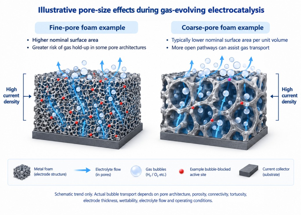
For low-to-moderate-rate electrocatalysis screening, a mid-range pore grade is a practical starting point. Finer pores may favour nominal surface area, whereas more open pore structures can favour electrolyte and gas transport as reaction rate increases. The optimum grade should be validated at the current density and flow conditions relevant to the intended experiment.
6. Pretreatment: degreasing, oxide removal and activation
As-received metal foam is not a clean electrochemical surface. Nickel foam in particular oxidises readily in air, forming a native nickel oxide layer, and manufacturing residues (rolling oils, handling contaminants) can also be present. Skipping pretreatment is one of the most common causes of poor catalyst adhesion and irreproducible baseline CVs in foam-based electrocatalysis work.
A standard nickel foam pretreatment sequence, drawn from established literature protocols, looks like this:
-
Cut the foam to the required size (see Section 7) before pretreatment, not after, so the cleaning solution reaches every exposed edge.
-
Degrease by sonicating in acetone for around 10 minutes to remove organic residues and handling contaminants.
-
Remove surface oxide with a dilute acid wash. Around 0.1 to 3 M hydrochloric acid for a few minutes is typical. Some protocols use an alkaline degreasing bath first (sodium hydroxide with phosphate, carbonate and silicate additives) followed by a separate dilute-HCl oxide-strip step; acetone sonication followed by a brief dilute-HCl treatment is a commonly reported starting procedure, but the appropriate protocol depends on the subsequent catalyst-growth chemistry and required surface state.
-
Rinse thoroughly with deionised water to remove residual acid, repeating two to three times.
-
Dry under an inert gas stream (argon or nitrogen) or in a vacuum oven at 60 to 80°C, and proceed to catalyst deposition promptly, since a freshly cleaned nickel surface will begin re-oxidising in air within hours.
A pitfall worth flagging explicitly: more acid treatment is not automatically better. Work examining nickel foam pretreatment in detail has shown that combining acid concentration with extended ultrasonication time can, counter-intuitively, grow a nickel oxide nanolayer rather than remove one. In one published study using mild HCl treatment under defined ultrasonic conditions, treatment beyond approximately 20 minutes produced a detectable NiO nanolayer by Raman spectroscopy even though obvious surface damage was not apparent by electron microscopy. Treat this as a protocol-specific warning rather than a universal 20-minute limit. Keep acid treatment brief and monitor electrochemical surface area rather than assuming that longer equals cleaner.
If your goal is not just cleaning but deliberate surface roughening, increasing the electrochemically active surface area of the bare nickel skeleton itself ahead of catalyst deposition, a plain dilute-HCl wash will not achieve this; it removes the oxide layer but leaves the underlying metal skeleton smooth. A mixed-acid etch (combining acetic, nitric, sulfuric and phosphoric acids) has been used specifically to roughen the nickel foam surface at the microstructural level, generating additional nanoscale features that a simple HCl clean does not produce. Choose the protocol that matches your actual objective: oxide removal alone, or oxide removal plus roughening.
Copper foam pretreatment for CO₂RR follows a related but distinct sequence, and it is worth being precise here because copper's relationship with its native oxide is more nuanced than nickel's. A published protocol for copper foam CO₂RR electrodes uses acetone sonication (around 10 minutes), a 2 M HCl wash (around 5 minutes), a deionised water rinse, drying under argon, and then, as an additional step not used for nickel foam, electropolishing in 85% phosphoric acid at 2.1 V for around 4 minutes using a carbon counter and reference electrode, to produce a smoother, more uniform copper surface ahead of CO₂RR testing.
The nuance: unlike nickel, where oxide removal is unambiguously desirable, copper's high surface area makes it prone to rapid re-oxidation (forming Cu₂O and CuO), and in some CO₂RR workflows this oxide is retained deliberately. Oxide-derived copper (OD-Cu), meaning copper that has been oxidised and then electrochemically reduced back to the metal while retaining structural and electronic signatures of that oxide history, is a recognised strategy for improving selectivity toward multi-carbon (C2+) CO₂RR products. If your protocol calls for OD-Cu, do not treat your pretreatment as complete once the visible oxide is gone; confirm which oxidation state you actually want present before drawing conclusions about "clean" versus "contaminated" surfaces.
Titanium-foam pretreatment is application-dependent. Degreasing with a suitable solvent and thorough rinsing are conservative starting steps, but acid etching or oxide removal is deliberately used in some coating and electroplating workflows. Do not assume that the native oxide must always be preserved or always be removed; follow a pretreatment protocol validated for the intended electrolyte, catalyst or coating process.
Activation or electrochemical preconditioning can improve repeatability when it forms part of a validated HER/OER protocol. The required number of cycles, scan rate and potential window depend on the catalyst and electrolyte; whatever procedure is selected should be kept identical across samples being compared.
After substrate preparation and catalyst loading, CV, CA/CP and EIS measurements can be performed using a suitable Potentiostat / Galvanostat.
7. Cutting, mounting and defining a reproducible geometric area
Metal foam is almost never used at its as-supplied sheet dimensions; it is cut down to fit a specific cell window, clamp geometry, coin-cell or pouch-cell fixture. Cutting introduces two practical risks that are easy to overlook: mechanical damage to the pore network at the cut edge, and loose metallic debris that contaminates both the electrode and the electrolyte if not removed.
A few practical points for cutting and mounting:
-
Use a clean blade, punch, or fine-toothed shears rather than tearing the foam, which can compress and seal pores at the cut edge, reducing the effective active area near the boundary.
-
After cutting, rinse gently to remove loose metallic particles generated during cutting, in a manner compatible with your downstream workflow (a brief deionised water rinse followed by the pretreatment sequence in Section 6 handles this in most cases).
-
Wear gloves throughout cutting and handling, both to protect yourself from sharp cut edges and to avoid introducing skin oils or contamination onto a surface you are about to characterise electrochemically, particularly for catalyst-coated foams.
-
Define your exposed geometric area deliberately, using a fixed clamp aperture, an O-ring seal, or a defined immersion depth, and keep that method identical across every sample in a comparative study. Because porous structures introduce distributed resistance and capacitance if the electrical contact is inconsistent, a loose or variable clamp connection can masquerade as a catalyst performance difference in impedance measurements when it is really a contact-quality artefact. For repeatable electrical contact and exposed-area control, consider an appropriate Electrode Clamp / Holder.
-
If your cell geometry, clamp aperture or exposed-area requirement is non-standard, cut-to-size requests are routine for metal foam suppliers; for ScienceGears' custom-sized metal foam option, share the target material, thickness, approximate pore structure and finished dimensions when requesting a quote so the recommended grade fits both your cell hardware and your intended reaction.
-
For compression-sensitive setups (foam clamped between current collector plates in a flow cell or pouch-style fixture), keep clamp compression consistent between samples; over-compression can partially collapse the pore structure at the contact face, changing both porosity and contact resistance in ways that are easy to miss unless you inspect the foam after disassembly.
-
Cell geometry, sealing and exposed electrode area can also be controlled using an appropriate Electrochemical Cell for the intended experiment.
8. Common pitfalls and how to catch them early
Assuming "nickel foam" means one fixed pore size and thickness. Commercial nickel foam is supplied across a wide range of gauges and pore grades. If a paper you are trying to reproduce does not specify thickness and pore size explicitly, treat that as a gap in the method, not a detail you can safely default on. Request the specific grade rather than ordering whatever is labelled generically.
Over-treating with acid under the assumption that more cleaning is always better. As covered in Section 6, extended acid exposure combined with ultrasonication can grow rather than remove nickel oxide. If your baseline CVs look inconsistent between batches, check whether your cleaning time has crept upward rather than assuming the catalyst synthesis is the variable at fault.
Confusing geometric area with electrochemically active surface area. A foam's high porosity means its true active surface area can be many times its geometric footprint, and that ratio changes with pore size, thickness and how thoroughly the interior is wetted. Reporting current density normalised only to geometric area, without at least noting this limitation, makes cross-study comparison unreliable. Where appropriate, double-layer capacitance can be used as a relative surface-area proxy when the compared samples have sufficiently similar surface chemistry. Avoid treating Cdl-derived ECSA as an absolute measure without an appropriate specific-capacitance assumption.
Ignoring bubble accumulation at high current density. A foam that performs well in slow-scan CV screening at low current density can behave quite differently under sustained high-current operation, where internal gas trapping becomes the dominant limitation rather than intrinsic catalytic activity. If your end application is industrial-relevant current densities, validate at those current densities, not only at screening-scale currents.
Inconsistent clamp contact between "identical" samples. As noted in Section 7, porous foam electrodes are unusually sensitive to contact quality because the current has to distribute through a 3D network rather than a flat, uniform interface. Variable clamping pressure between samples is a frequent, under-reported source of scatter in reported impedance and polarisation data.
Treating oxide as universally undesirable. Section 6 covered this for copper specifically, but the broader principle holds across metals: whether a native or induced oxide layer helps or hurts your measurement depends on the reaction and the desired active phase. Confirm the target surface chemistry for your specific catalyst system before optimising a pretreatment protocol around oxide removal by default.
9. Decision matrix: choosing your foam
| Application | Recommended metal foam | Specific product | Key rationale | Key constraint |
|---|---|---|---|---|
| Alkaline HER screening | Nickel foam | Nickel Foam | Stable, conductive, well-characterised substrate for HER catalyst growth in alkaline media | Confirm exact thickness/pore grade with supplier; not published as a fixed spec |
| Alkaline OER screening | Nickel foam | Nickel Foam | Widely used bifunctional-compatible backing for hydroxide and phosphide OER catalysts | Native NiO layer must be managed deliberately, not assumed removed |
| Industrial-relevant water splitting (high current density) | Iron-nickel foam | Iron Nickel Foam | Robust backing with published porosity (75 to 98%) and open-cell rate (98% or higher) suited to sustained gas evolution | Thicker gauge (2 mm) increases internal bubble path length |
| Cu-based CO₂RR screening | Copper foam | Copper Foam | Useful when copper is intentionally part of the catalytic phase. | Copper should not be presented as the generally preferred substrate for CO- or formate-selective CO₂RR. |
| CO₂RR toward C2+ products (ethylene, ethanol) | Copper foam (oxide-derived) | Copper Foam | Oxide-derived Cu can show enhanced C₂+ selectivity in published work. Proposed contributors include reconstructed morphology, grain boundaries, low-coordinate sites and residual or subsurface oxygen; the exact active-state mechanism remains under discussion. | Pretreatment must preserve, not strip, target oxide state |
| Corrosion-sensitive or acidic electrolysis | Titanium foam | Titanium Foam Sheet | Passivating oxide layer gives corrosion resistance; published spec (0.5 mm, 100 µm aperture) | Do not over-etch; aggressive acid removes the protective layer you selected it for |
| Flow-through or gas-diffusion style electrodes | Titanium foam | Titanium Foam Sheet | Fine 100 µm aperture and permeable structure suit flow-through architectures | Compressive strength should be considered when defining fixture and clamp loading; allowable clamp pressure also depends on contact area, support geometry and acceptable foam deformation. |
| Cobalt-based OER catalyst screening | Cobalt foam | Cobalt Foam Electrode | Cobalt surfaces are well characterised in alkaline electrocatalysis for rapid materials screening | Stability is electrolyte- and potential-dependent; confirm before extended cycling |
| High-temperature or filtration-adjacent electrochemical trials | Iron-nickel foam | Iron Nickel Foam | Chemical robustness suited to harsher operating environments | Bulk density range (0.1 to 0.8 g/cm³) varies by grade; confirm for your loading calculations |
| Bifunctional overall water splitting benchmarking | Nickel foam or iron-nickel foam | Nickel Foam / Iron Nickel Foam | Both are established backbones for two-electrode overall water splitting cells in the literature | Select each electrode substrate for compatibility with its respective half-reaction and report the substrate background. Symmetric or asymmetric substrate selection should be intentional and documented. |
| Rapid catalyst-support materials screening (any metal) | Whichever base metal matches your target catalyst chemistry | See product family | Foam format lets you screen multiple loadings on a consistent 3D scaffold before optimising | Keep pretreatment, wetting time and clamp compression identical across the screening set |
| Custom cell geometry (coin, pouch, flow-cell windows) | Customised size metal foam | Metal Foam Electrodes category | Cut-to-size supply avoids introducing cutting-edge damage variability between labs | Specify material, thickness, pore structure and finished dimensions in your quote request |
| Ammonia oxidation reaction studies | Nickel foam | Nickel Foam | Reported substrate for ammonia oxidation alongside OER in mild-acid-treated nickel foam studies | Surface pretreatment window (oxide layer thickness) affects activity; keep treatment time controlled |
| Impedance / EIS-focused comparative studies | Match metal to reaction, prioritise thickness consistency | See relevant rows above | Distributed resistance and capacitance in porous electrodes are highly sensitive to contact and wetting consistency | Fix clamp geometry, compression and wetting time across the full comparison set |
10. FAQ
What is the difference between pore size and PPI on a metal foam datasheet?
Pore size (or aperture) is a direct linear measurement of an individual pore opening, usually in micrometres or millimetres. PPI (pores per inch) is a count-based descriptor of how many pores appear along a linear inch of the foam. The two are related but not identical, since pore shape and distribution affect how a given aperture translates into a PPI figure; when comparing foams from different suppliers, check which figure is quoted and, where possible, ask for both.
How do I choose between nickel, copper, titanium, iron-nickel and cobalt foam for electrocatalysis?
Start with the reaction, electrolyte and intended role of the foam. Nickel foam is widely used for alkaline HER/OER but contributes its own electrochemical response. Copper foam is particularly relevant when copper is intentionally part of the CO₂RR catalytic phase, especially for C₂+ chemistry. Titanium offers useful corrosion resistance in many systems, while iron–nickel and cobalt foams should be selected according to reaction chemistry, operating conditions and the required mechanical properties.
Does a finer pore size always give better electrocatalytic performance?
No. Finer pores increase nominal surface area but trap gas bubbles more readily at appreciable current densities, which reduces both mass transfer and the fraction of the surface actually participating in the reaction at any moment. Coarser pores release bubbles more effectively but carry less surface area per unit volume. The right choice depends on your target current density, not on maximising pore density by default.
How long should I acid-treat nickel foam before use?
There is no universal treatment time. Use a literature- or process-validated protocol and keep acid concentration, temperature, sonication conditions and treatment time constant. In one mild-HCl/ultrasonication study, a NiO nanolayer became detectable after treatment beyond approximately 20 minutes, illustrating why longer treatment should not automatically be assumed to produce a cleaner surface.
Do I need to remove all surface oxide before using copper foam for CO₂RR?
Not necessarily, and this depends on your target product distribution. Some CO₂RR protocols deliberately retain oxide-derived copper character to improve selectivity toward multi-carbon products, rather than aiming for a fully metallic, oxide-free surface. Confirm the surface chemistry your specific catalyst system requires before choosing a pretreatment protocol built around complete oxide removal.
What are the main safety and handling considerations when cutting and mounting metal foam?
Wear gloves to avoid sharp cut edges and to prevent skin contamination of catalyst-coated surfaces, use a clean blade or punch rather than tearing the material, rinse away loose metallic debris generated during cutting, and confirm your cell can vent safely if you are running high currents or gas-evolving reactions. Always check chemical compatibility between the foam, your electrolyte and your operating temperature range before starting.
11. Expert support: how ScienceGears works alongside your research
ScienceGears is led by a PhD-trained electrochemist with direct bench experience selecting, pretreating and troubleshooting porous metal substrates for HER, OER and CO₂RR workflows, so the guidance you get reflects what actually holds up under real cell conditions, not just what a datasheet claims.
Confirming the right foam before you order If you are unsure whether nickel, copper, titanium, iron-nickel or cobalt foam fits your reaction, or which thickness and pore grade suits your target current density, our technical team will work through your electrolyte, reaction and cell geometry with you before you commit to a purchase. Talk to our technical team →
Pretreatment protocol verification Send us your planned degreasing, acid-clean or electropolishing sequence and target catalyst system, and we will flag anything likely to cause over-oxidation, under-cleaning, or oxide-state mismatches with your intended chemistry before you spend bench time on it.
Complete system supply
-
Potentiostats / Galvanostats for CV, CA/CP and EIS characterisation
-
Electrochemical Cell options for sealed, gas-managed or flow-assisted foam electrode testing
-
Electrode Clamp/Holder hardware for reproducible, low-contact-resistance mounting
Local AU/NZ stock: same-day dispatch ScienceGears holds core electrochemistry consumables and accessories locally for researchers across Australia and New Zealand, with same-day dispatch on in-stock items so a substrate or hardware gap does not stall an experiment already underway. Custom-cut foam and less common grades are sourced on request with clear lead times communicated up front.
"The foam is not a passive backdrop for your catalyst. Its thickness and pore size actively decide how much of your catalyst ever gets to react." ScienceGears Technical Team
12. Further reading
13. Get in touch
If you are scoping a new electrocatalysis build and want a second opinion on substrate selection, pretreatment protocol, or cell hardware, reach out before you order.