

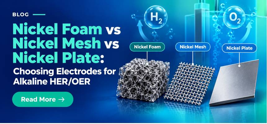
By the end of this article, you will be able to choose between nickel foam, nickel mesh, and nickel plate for a specific alkaline HER or OER experiment, justify that choice in terms of surface area, current collection, catalyst loading, gas release, durability, and cleaning, and know exactly how to prepare and cut the electrode before it goes into your cell.
The real trade-off: why nickel format changes your HER/OER result
A postdoc handed a new HER catalyst usually reaches for whatever nickel substrate is already sitting in the drawer. That choice is rarely neutral. Swap a flat nickel plate for a porous nickel foam under the same catalyst loading, and you can shift the apparent overpotential by tens of millivolts, change the shape of your Tafel plot, and alter how the electrode behaves once you move from a three-electrode screening cell to a higher-current, flow-through configuration. None of that is really about the catalyst. It comes down to the substrate.
Nickel foam, nickel mesh and nickel plate are all high-purity, corrosion-resistant nickel formats, and all three get used as working-electrode substrates, current collectors and catalyst supports for hydrogen evolution (HER) and oxygen evolution (OER) research in alkaline electrolyte. The confusion isn't really about whether nickel is the right base metal, since in alkaline media it usually is. It's about which physical architecture matches the question you're actually asking: are you screening a catalyst's intrinsic activity, trying to maximise loading, or trying to reproduce how an industrial alkaline electrolyser electrode behaves at high current density.
This article works through six practical angles: surface area, current collection, catalyst loading, gas bubble release, durability, and cleaning and cutting. It ends with a decision matrix you can use directly at the bench.
Related: ScienceGears' full range of metal foam electrodes and current collectors.
Surface area and electrochemically active area across foam, mesh and plate
The pain point here is simple: two electrodes with the same geometric footprint can carry very different amounts of real surface, and reporting current density against the wrong area is one of the most common sources of irreproducible HER/OER data between labs.
For comparison between formats, use the projected geometric area consistently and state which faces are exposed. Nickel plate provides the simplest, most clearly defined footprint. Nickel mesh increases wetted metal area through its open wire or expanded structure, but the increase depends on mesh count, wire diameter, open area and exposure geometry. Nickel foam provides a three-dimensional porous network with substantially greater accessible surface area per projected footprint, although the exact value depends strongly on pore structure, thickness and wetting.
That extra area is genuinely useful. Published work on nickel-foam-supported HER and OER catalysts consistently attributes part of the improved performance to the fine roughness of the individual foam struts, which increases the surface available for the reaction beyond what a flat substrate of the same footprint could offer. Foam thickness matters too. One controlled study of bare nickel foam cathodes found that increasing foam thickness from 0.3 mm to 2.0 mm increased HER current density by roughly seventy-one percent at −1.0 V versus the reversible hydrogen electrode, consistent with more of the foam's internal area becoming electrochemically accessible as thickness increases.
A recent mechanistic study on Fe-modified nickel electrodes found that the activity increase associated with precatalytic surface roughness was not explained primarily by greater ECSA. Under the conditions of that study, undercoordinated step sites favoured formation of OER-active NiOOH phases, while flatter Ni(111) regions favoured less-active NiO. In practical terms, don't assume a higher-ECSA substrate will automatically translate into a proportionally lower overpotential. When ECSA normalisation is used, report the estimation method and experimental conditions clearly. Double-layer-capacitance-derived ECSA is best treated as a comparative metric within a controlled study rather than an absolute measurement of the ‘true’ active surface area.
Working rule of thumb: if the experiment lives or dies on intrinsic catalytic activity per real active site, plate or mesh give you a cleaner, more geometrically defined baseline. If it's about maximising total active area and total current per unit of footprint, closer to how an industrial electrode actually operates, foam is the format built for that job.
Explore ScienceGears' Nickel Foam, Nickel Mesh and Nickel Sheet / Plate pages for current thickness, pore size and dimension options.
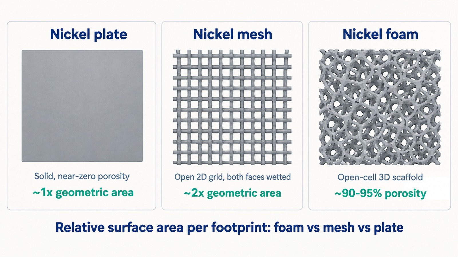
Figure 1. Relative surface area per footprint across the three formats. Schematic for illustration only, not to scale.
Current collection and iR drop: how format changes your compliance voltage
A researcher chasing a clean Tafel slope who instead sees a curved, high-resistance-looking polarisation curve often blames the catalyst, when the actual culprit is current distribution through the substrate.
Nickel plate provides a continuous, low-resistance current path. Nickel mesh can also provide effective current collection, although resistance and directional behaviour depend on wire or strand geometry, mesh construction and the quality of the electrical contact. Current entering at a clamp travels through a continuous or near-continuous metal path to every point of the working surface, so the ohmic contribution from the substrate itself is small and predictable. Nickel foam is more complicated. Its struts form a tortuous, three-dimensional conduction network, and the effective in-plane and through-plane resistance depends on strut thickness, pore size, and critically, how well your catalyst layer is electrically connected back into that network. A thick catalyst coating deep inside a foam pore can be electrochemically active but electrically starved if the local nickel strut network around it is sparse, which shows up as extra apparent resistance that has nothing to do with electrolyte conductivity.
This matters most at higher current densities, where even small resistances become large voltage penalties. As current density increases, even relatively small substrate and contact resistances can contribute a measurable voltage penalty. The current density at which this becomes important depends on electrode geometry, contact design, electrolyte conductivity, temperature and overall cell configuration. Practical implication: always use a proper current-collection contact (a full-width clamp or a welded/crimped tab, not a single alligator clip on one corner) on foam electrodes, and validate your reported iR-corrected data with electrochemical impedance spectroscopy rather than assuming the substrate's contribution is negligible.
Mesh occupies a useful middle ground. It offers a genuinely lower-resistance, more uniform current path than foam while still presenting an open, higher-area structure than solid plate, which is one reason mesh and expanded-metal architectures are increasingly explored as practical current-collector and gas-channel elements in water electrolysis cell design.
A stable, repeatable electrical connection also depends on the electrode clamp or holder you use. Thin foam and mesh in particular need a clamp with adjustable clipping thickness to maintain consistent contact pressure across repeat experiments. If your work sits closer to the battery side of electrochemistry, the same current-distribution logic applies to porous and foil-based current collectors, though that's a separate product line from the HER/OER electrodes covered here.
Catalyst loading and adhesion on each nickel format
The question that comes up in almost every catalyst-development meeting is: how much can I actually put on this electrode before it falls off or stops mattering?
Nickel foam's open, three-dimensional pore network gives it by far the highest practical catalyst-loading capacity of the three formats. Researchers routinely use foam as a scaffold for hydrothermally grown nanoarrays, electrodeposited films and drop-cast slurries, specifically because the struts provide many internal anchor points, and the pore volume can physically accommodate a thicker catalyst layer than a flat surface ever could. This is why so much of the published nickel-foam-supported HER/OER literature reports catalysts grown directly and conformally on the foam struts rather than deposited as a discrete film.
That same openness creates a mechanical trade-off. A catalyst layer that only bridges across the mouth of a pore, rather than conforming to the strut itself, is vulnerable to being physically dislodged by the gas bubbles generated during HER or OER (more on this in the section on gas bubble release). Once dislodged, it's genuinely gone, since there's no flat backing layer holding it in place. Mesh and plate hold proportionally less total catalyst mass for the same footprint, but what they do hold tends to adhere more predictably, because the deposition geometry is simpler and more uniform, which makes coating thickness, mass loading and film continuity easier to control and reproduce between electrodes.
For quantitative structure to activity studies where you need to know your catalyst mass loading precisely (mg cm⁻²) and be confident it hasn't partially detached during testing, plate or mesh substrates make that bookkeeping considerably more tractable. For studies where the goal is simply to load as much active catalyst as possible onto a compact footprint, for example prototyping a high-current cathode, foam is the appropriate choice, provided you validate adhesion under realistic gas-evolution conditions rather than only under quiescent voltammetry.
Gas bubble release and mass transport at high current density
This is the section that changes most researchers' assumptions, because it directly contradicts the instinct that "more surface area always wins."
Every HER and OER experiment generates gas at the electrode, and how that gas escapes has a first-order effect on performance once current density climbs. In an open, flat geometry like nickel plate, bubbles nucleate, grow and detach with a relatively unobstructed path to the bulk electrolyte. In nickel foam's disordered three-dimensional pore network, published high-speed imaging and modelling studies show a different behaviour. Bubbles generated deep inside the structure can coalesce and become physically trapped among the struts rather than escaping cleanly, creating a barrier between the electrolyte and the active sites behind it and increasing ohmic resistance in the process. One review of porous electrode design in alkaline water electrolysis notes that in foams with pore sizes below roughly 1,000 µm, forced electrolyte convection is often required simply to shorten bubble residence time enough to avoid this masking effect, and that increasing electrolyte flow to compensate carries its own cost in pumping losses.
This is precisely why a comparative modelling and imaging study concluded that foam electrodes may not be well suited to the highest current densities used in industrial-style alkaline electrolysis testing, even though the same foam performs well at moderate current densities where bubble generation rates are lower and easier to clear. Mesh and expanded-metal architectures, by contrast, present a comparatively open, less tortuous path for detached bubbles to rise away from the electrode surface, and are increasingly investigated as a practical compromise between surface area and bubble evacuation in cell designs targeting high current density.
Gas accumulation can become increasingly important as current density rises, particularly in porous electrodes with tortuous or poorly connected gas-release pathways. Nickel foam performance therefore depends strongly on pore structure, thickness, wettability, orientation and electrolyte flow. Some foam architectures exhibit significant bubble trapping, whereas appropriately designed or thicker foams can improve bubble detachment and perform effectively at high current density. Rather than applying a universal current-density cut-off, compare candidate electrode architectures under the intended cell and flow conditions.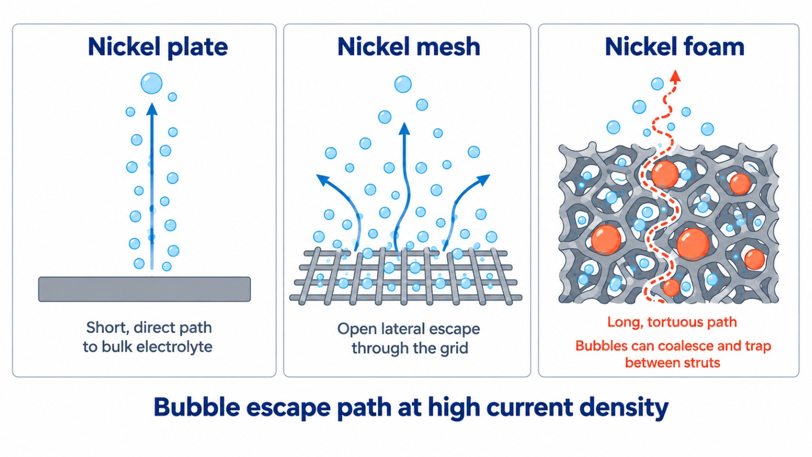
If your programme is moving toward full-cell or stack-level testing rather than three-electrode screening, ScienceGears' AlkalineWE alkaline water electrolyser test stations are built specifically to characterise gas-liquid behaviour and current-density performance under realistic circulating-electrolyte conditions.
Durability and corrosion behaviour in concentrated KOH
Nickel's popularity in alkaline electrochemistry comes substantially from its corrosion resistance in concentrated hydroxide electrolyte, but "nickel is corrosion resistant" is not the same statement as "all nickel electrode formats degrade identically over a long test."
Nickel surface chemistry depends strongly on electrode potential and operating history. Under anodic/OER conditions, Ni(OH)₂/NiOOH-related surface phases are important, whereas the cathodic/HER surface experiences a different electrochemical environment. Long-term behaviour is influenced by potential history, electrolyte concentration, temperature, impurities and start-stop cycling. For foam and mesh, mechanically thin struts, wires and junctions should therefore be inspected during extended testing in addition to monitoring electrochemical performance.
Thickness is a genuine lever here. Mesh sits between foam and plate: its wire junctions can behave similarly to foam struts under prolonged operation, but its simpler, more open geometry generally makes any localised loss easier to inspect visually and by weight change between test intervals.
For durability studies intended to run for tens to hundreds of hours, plan to track mass loss and visual strut or wire integrity at fixed intervals regardless of format, and be cautious about over-interpreting a small increase in overpotential late in a long run as a catalyst-degradation signal when it may instead reflect substrate-level restructuring, particularly on foam and mesh.
Cleaning and activation protocols before you load a catalyst
An electrode straight out of the packet is not ready for catalyst deposition or blank electrochemical testing. Residual rolling oils, handling contaminants and a thin native oxide layer will all distort your baseline and can cause poor catalyst adhesion.
A practical starting sequence is outlined below, but nickel pretreatment is not universal. Solvent cleaning, acid treatment and electrochemical conditioning can themselves change surface chemistry and morphology, so the selected protocol should be validated for the specific substrate and applied consistently to all comparative electrodes.
Cleaning nickel plate and nickel mesh
- Degrease by ultrasonication in acetone for 10 minutes, then in ethanol for 5 minutes.
- Rinse thoroughly in deionised or Milli-Q water.
- Immerse in 0.5 to 1 M HCl for 3 to 5 minutes to strip the native oxide layer, then rinse again immediately and thoroughly. Don't let the electrode air-dry with acid still on the surface.
- If electrochemical conditioning is used, report the reference electrode, potential window, scan rate, cycle number, electrolyte and temperature explicitly. The conditioning window should be selected for the stated reference electrode and experimental objective rather than applying one universal potential range.
Cleaning nickel foam
For nickel foam, use a cleaning method that removes contamination without mechanically damaging or unintentionally modifying the porous structure. Prolonged sonication should not automatically be assumed to be beneficial; inspect the foam after pretreatment and use the mildest validated procedure consistent with the experiment. Dry foam carefully under a gentle nitrogen stream or in a low-temperature oven rather than compressed air, which can physically deform thin struts.
Chemical treatments intended to modify nickel foam should be considered separately from routine cleaning. In particular, Fe-containing treatments such as FeCl₃ can introduce iron species that substantially alter Ni-based OER activity and should therefore be reported as intentional chemical/electrocatalytic modification rather than simple surface roughening. That's a surface-engineering step in its own right, distinct from routine pre-deposition cleaning, and it should be reported separately in your methods section rather than folded into "standard cleaning."
Cutting, shaping and mounting nickel electrodes on the bench
Getting a clean, reproducible geometric area out of raw stock is a small step that causes a disproportionate amount of irreproducible data when it's done carelessly.
Cutting nickel plate
Nickel plate is the most forgiving format to cut precisely. Metal shears, a guillotine, or laser cutting all give clean, burr-free edges. For plate electrodes, the projected geometric footprint can be measured accurately with callipers, but the electrochemically exposed area also depends on whether one face, both faces and the edges are exposed or masked. Report the exposed-area definition explicitly. For disc electrodes intended for a plate clamp, a punch or laser-cut disc gives the most dimensionally consistent results between replicates.
Cutting nickel mesh
Nickel mesh cuts easily with sharp scissors or shears, but take care at the cut edge. Open wire ends can fray, and a frayed edge both changes your true exposed area unpredictably and can pierce through thin gaskets or membranes in a sealed cell. A light deburr or a laser-cut edge (which fuses the wire ends) avoids this. Mesh is also easy to hand-shape around curved cell geometries, which plate cannot do without specialist forming.
Cutting nickel foam
Nickel foam is the format most likely to be damaged by an unplanned cutting method. Standard scissors or shears tend to crush and smear the open pore structure at the cut edge, locally collapsing porosity exactly where your electrode meets your clamp or seal. Laser cutting gives the cleanest result and is strongly preferred wherever available. Where only manual cutting is possible, use a sharp single-edge blade with firm, single-pass pressure rather than a sawing motion, and inspect the cut edge under magnification before use.
For all three formats, always confirm your final geometric area by direct measurement (callipers or imaging) rather than assuming the nominal cut dimension, and record the exact exposed area used in every measurement. This single habit resolves a surprising fraction of "my results don't match the literature" troubleshooting conversations. ScienceGears' full electrochemistry accessories range, including plate clamps and holders, is built to accommodate custom-cut nickel electrodes across all three formats.
Decision matrix: matching nickel format to your experiment
| Application | Recommended format | Specific product | Key rationale | Key constraint |
|---|---|---|---|---|
| Catalyst screening in a three-electrode cell | Nickel plate, or mesh where an open substrate is intentionally required | Nickel Sheet / Plate or Nickel Mesh | Plate provides the most clearly defined geometric baseline; mesh can be used where an open structure is required, but its wetted area depends on mesh geometry. | Lower total catalyst-loading capacity than foam |
| High-loading electrodeposited or hydrothermally grown catalyst films | Nickel foam | Nickel Foam | Open 3D scaffold accommodates thick, high-mass-loading deposits with many anchor points | Bubble entrapment risk rises sharply above roughly 200 to 300 mA cm⁻² |
| Industrial-style OER anode at high current density | Nickel plate or thin mesh | Nickel Sheet / Plate | Open, short bubble-release path preserves mass transport at high current density | Lower intrinsic active area than foam at the same footprint |
| HER cathode for a lab-scale alkaline electrolyser mimic cell | Nickel foam | Nickel Foam | High roughness factor lowers apparent overpotential at low-to-moderate current density | Needs forced electrolyte flow or a thinner foam above roughly 200 to 300 mA cm⁻² |
| Post-mortem XPS or XRD characterisation of a spent catalyst | Nickel plate | Nickel Sheet / Plate | Flat, uniform surface avoids topographic shadowing artefacts | Lower total active area for surface-sensitive signal averaging |
| Blank or background CV measurements | Nickel plate | Nickel Sheet / Plate | Reproducible, low-noise baseline with minimal geometric uncertainty | Not representative of a porous industrial electrode's behaviour |
| Long-duration stability testing (hundreds of hours) | Nickel mesh | Nickel Mesh | Reasonable balance of area, gas release and mechanical robustness | Wire-crossing junctions are localised degradation points to monitor |
| Cost-sensitive, high-throughput catalyst screening | Nickel mesh | Nickel Mesh | Easy to cut into many geometrically identical coupons economically | Lower per-coupon surface area than an equivalent foam coupon |
| Zero-gap or flow-cell electrolyser prototyping | Nickel foam | Nickel Foam | Provides structural support, in-plane conductivity and internal flow pathways | Best paired with forced convection or a thinner foam format |
| Counter electrode in a three-electrode alkaline cell | Nickel plate or mesh | Nickel Sheet / Plate | Conductive, alkaline-compatible and readily available in large geometric areas | Not typically catalyst-loaded, so oversize the geometric area |
| Custom-shaped or curved electrode for bespoke cell hardware | Nickel mesh | Nickel Mesh | Flexible enough to hand-form around curved cell geometries | Thin cross-section can distort under excessive clamping pressure |
| Bench replicate studies needing identical geometric area | Nickel plate | Nickel Sheet / Plate | Laser- or punch-cut discs are the most dimensionally consistent between replicates | Least catalyst-loading headroom of the three formats |
| Rapid comparative screening across many catalyst formulations | Nickel plate | Nickel Sheet / Plate | Simple, uniform deposition geometry keeps mass-loading bookkeeping tractable | Requires more careful thin-film adhesion control than foam |
| Combined bifunctional overall-water-splitting cell (HER cathode + OER anode) | Nickel foam (cathode) paired with nickel plate or mesh (anode) | Nickel Foam and Nickel Sheet / Plate | Matches the HER side's loading needs with the OER side's bubble-release needs | Requires validating each electrode's iR contribution separately |
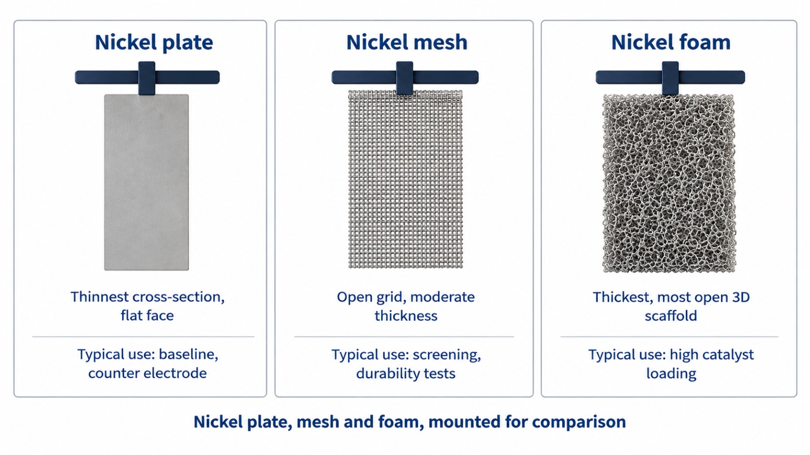
Figure 3. Relative thickness and openness of the three formats, shown mounted in a clamp for scale.
Frequently asked questions
Which nickel electrode format gives the highest electrochemically active surface area?
Nickel foam, by a wide margin, because of its open three-dimensional pore network. That said, higher ECSA doesn't automatically translate into a proportionally lower overpotential. Normalise by real active area, not geometric area, before comparing formats, and remember that some of a rough surface's activity gain comes from the catalytic phase it favours rather than area alone.
Can I use nickel foam at high current density without losing performance?
Below roughly 100 to 200 mA cm⁻² foam generally performs well. Above that range, gas bubbles can coalesce and become trapped within the pore network, masking active sites and increasing resistance. Forced electrolyte flow, a thinner foam, or switching to mesh or plate for the high-current regime are the usual fixes.
How much catalyst loading can nickel foam hold compared with mesh or plate?
Foam holds substantially more total catalyst mass per unit footprint because of its internal pore volume and strut surface area. Mesh and plate hold less in absolute terms but generally offer more predictable, more easily quantified adhesion, which matters for precise mass-loading studies.
Do I need different cleaning steps for foam, mesh and plate before loading a catalyst?
The core sequence, degrease, rinse, mild acid strip, conditioning CV cycles, is the same across all three, but foam needs longer ultrasonication to clear contaminants from inside the pore network and a more dilute acid step to avoid over-etching thin struts.
Which format is best for flat, reproducible baseline measurements such as XPS, XRD or blank CVs?
Nickel plate. Its flat, uniform surface (see the decision matrix) avoids the topographic and shadowing artefacts that porous or open-grid substrates can introduce, and its geometric area is the easiest of the three to measure and report precisely.
Can nickel mesh or plate be cut and shaped in-house, or does it need to be ordered pre-cut?
Both can be cut in-house with basic lab tools: shears or a guillotine for plate, sharp scissors or shears for mesh. Laser-cut edges give the cleanest, most reproducible result for both, and are strongly preferred for foam specifically, since manual cutting tends to crush the open pore structure at the cut edge.
Expert support: how ScienceGears works alongside your research
ScienceGears is led by a PhD-trained electrochemist with direct bench experience running HER and OER studies across nickel foam, mesh and plate substrates, in three-electrode screening cells and in higher-current alkaline test platforms. We understand that the "right" format is rarely a fixed answer. It depends on your current-density range, your loading strategy and what you ultimately need the data to demonstrate.
Substrate selection before you order
Talk to our technical team before committing to a format, especially if you're moving from screening-scale to higher-current testing, or scaling a catalyst that was developed on one substrate onto another. We'll help you match pore size, thickness and format to your expected current-density range and cell geometry. Talk to our technical team →
Bubble-masking and resistance diagnosis
If your polarisation curve shows unexpected upward curvature at higher current density, we can help you work through whether the cause is substrate-level bubble entrapment, contact resistance, or catalyst-layer detachment, and recommend the format or flow configuration to isolate the answer.
Complete system supply
- Nickel Foam
- Nickel Mesh
- Nickel Sheet / Plate
- Electrode Clamp / Holder
- Electrochemistry Accessories (cells, holders and related hardware)
- Metal Foam Electrodes & Current Collectors (Cu, Al, Fe-Ni, Ti variants)
- AlkalineWE Alkaline Water Electrolyser Test Stations
Global supply, with local support for Australia and New Zealand
ScienceGears supplies nickel foam, nickel mesh and nickel sheet/plate to researchers across Australia and New Zealand and ships internationally. Contact our team for current stock, cut-to-size availability and dispatch timing.
“The substrate is not a passive backdrop to your catalyst. It decides how much of your catalyst's true performance you actually get to see.”
Further reading
- Metal foam electrodes and porous current collectors: nickel, copper, aluminium, iron-nickel and titanium foam options compared
- Working electrodes for electrochemistry: disc, plate, rod and L-type formats and how to choose between them
- Electrochemistry accessories: cells, clamps and holders for custom electrode geometries
- AlkalineWE alkaline water electrolyser test stations: moving from screening cells to single-cell and stack-level testing
Related but outside this blog's scope: copper, titanium, iron-nickel and stainless-steel foam and mesh variants; PEM and AEM (rather than alkaline) water electrolysis substrates; noble-metal (Pt/Ir) catalysts; acidic-media HER/OER testing; and small-format substrates such as microelectrodes or disc electrodes, which serve a different, lower-current diagnostic purpose. These are genuinely adjacent topics, but they aren't the nickel-in-alkaline-media comparison this article set out to make.
Get in touch
Have a specific alkaline HER/OER setup you're trying to configure, whether that's a screening cell, a flow cell, or a scale-up from lab bench toward a test station? Talk to our technical team or request a quote for nickel foam, mesh or plate in the thickness and pore size your experiment needs. We supply researchers across Australia and New Zealand and ship internationally on request.
ScienceGears Pty Ltd
Supplying research-grade electrochemistry and hydrogen R&D equipment to researchers in Australia and New Zealand, with international shipping available. Website: www.sciencegears.com.au