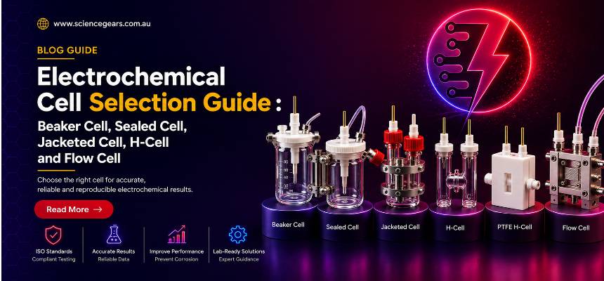


By the end of this article, you will be able to pick a photoelectrochemical cell geometry — window material, chamber type, illumination path, reference electrode position, jacket, and volume — that matches your photoelectrode, your electrolyte, and the measurement you are actually trying to make, rather than defaulting to whatever cell happens to be on the bench.
1. Why cell geometry decides your data, not just your chemistry
A photoanode that looks promising in one cell can look mediocre in another, without a single change to the catalyst. The difference is usually not chemistry. It is geometry. Where the light enters, how far the reference electrode sits from the working electrode, whether the counter compartment shares gas headspace with the working compartment, and whether the electrolyte temperature drifts over a three hour chronoamperometry run: each of these is a property of the cell, not the material.
This matters because photoelectrochemical (PEC) measurements stack two sources of error that a conventional dark electrochemical cell does not have to deal with. First, the illumination path adds an optical variable (window absorbance, reflection losses, and beam alignment) on top of the usual electrochemical variables. Second, most PEC reactions (water splitting, CO₂ reduction, photocatalytic degradation) evolve gas, so containment and compartment separation start to matter in a way they rarely do for a simple cyclic voltammogram in a beaker.
The rest of this guide works through the choices in the order they usually come up when specifying a cell: window material, containment, compartment separation, illumination direction, reference electrode position, and volume. Defining these parameters before the experiment can prevent avoidable reruns and improve reproducibility.
2. Window material: quartz versus borosilicate, and why the cut off matters
Every photoelectrochemical cell needs an optical window, and the two materials on offer are fused quartz and borosilicate glass. The decision is not cosmetic.
Quartz stays transparent much further into the ultraviolet than borosilicate. Fused silica has a wide electronic band gap of roughly 9 eV, which corresponds to an intrinsic absorption edge well below 150 nm; in practice, trace metallic impurities and point defects push the usable cut off of commercial synthetic quartz to somewhere around 190–200 nm, with high purity grades holding useful transmission even shorter. Borosilicate glass, by contrast, has a much narrower band gap of around 4 eV, and its transmission falls away sharply from roughly 310–320 nm. The exact figure depends on thickness and grade, but the practical consequence is the same: below about 320 nm, borosilicate is functionally opaque.
For visible-light PEC measurements, borosilicate may be adequate when the wavelengths of interest remain within its useful transmission range. However, semiconductor band gap alone does not determine the window requirement: BiVO₄, haematite and other photoabsorbers can also respond to higher-energy, shorter-wavelength photons. Match the window transmission curve to the illumination spectrum and the wavelength range being measured. The picture changes for wide band gap semiconductors such as titanium dioxide (band gap around 3.0–3.2 eV, absorption edge near 380–410 nm) or for any experiment measuring an incident photon to current efficiency (IPCE) spectrum down into the near UV. For IPCE or other wavelength-resolved measurements extending into the UV, attenuation by the window can suppress part of the measured response. Check the actual transmission curve of the window material and thickness against the wavelength range of interest.
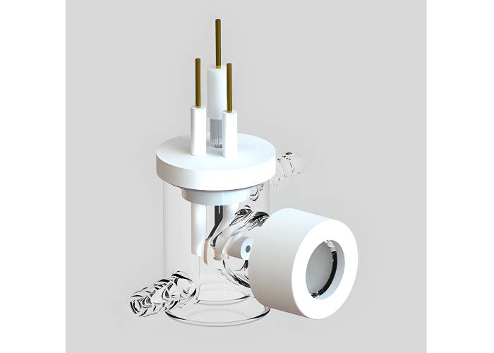
A second, less obvious issue is stray absorbance from the cell body itself. A cell built from borosilicate glass with only the illuminated window swapped for quartz still has a borosilicate body surrounding the electrolyte and, on multi window designs, the frame between windows. That body can contribute its own absorbance and scattering to a UV measurement even when the working window is quartz, which is one reason all quartz cell bodies exist for demanding optical work: with no borosilicate anywhere in the light path, there is nothing left to subtract out of the baseline. ScienceGears’ Photoelectrochemical Cell (Quartz) is built this way: full quartz construction with four sided optical transparency, intended for multi directional illumination and UV–Vis or Raman work where the body, not just the window, needs to be optically clean.
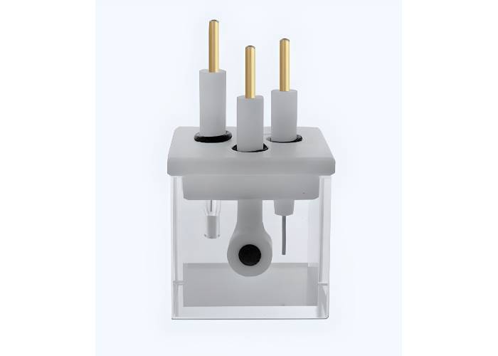
For most routine photoanode or photocathode screening in the visible range, a 24 mm quartz window set into a borosilicate or PTFE body is the standard and economical choice, and it is what the majority of ScienceGears’ PEC range uses: the Unsealed Type, Sealed Type, and the jacketed and H-type variants covered below. Reserve the all-quartz body for applications requiring extended UV transmission, high optical purity, multi-directional optical access or improved thermal-shock resistance. For strongly alkaline or otherwise aggressive electrolytes, verify material compatibility separately; a PTFE-bodied cell may be preferable where optical access is required only through the quartz window.
3. Sealed, unsealed, or jacketed: matching containment to the reaction
Containment is the next decision, and it is largely independent of window material. You can get quartz windows on unsealed, sealed, or jacketed bodies.
Unsealed (open top) cells
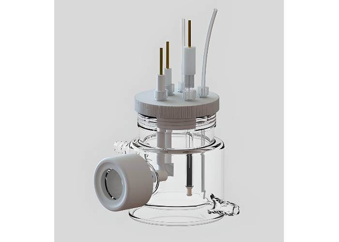
Unsealed cells trade gas tightness for speed of access. The Photoelectrochemical Cell – Unsealed Type and the Jacketed Photoelectrochemical Cell – Unsealed Type suit method development, electrode swap heavy screening campaigns, and teaching demonstrations, where the ability to lift an electrode out, rinse it, and drop it back in without breaking a seal outweighs the need to exclude atmospheric oxygen. They are a poor fit for anything that evolves or consumes gas quantitatively, because product gas escapes to the room instead of being collected or purged in a controlled way.
Sealed cells
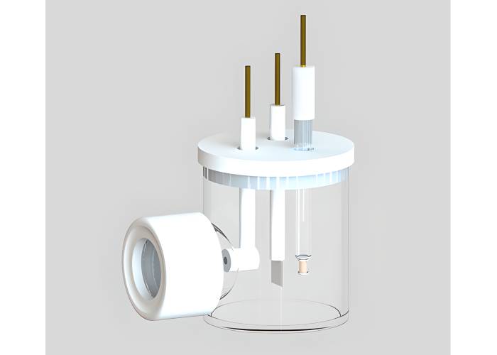
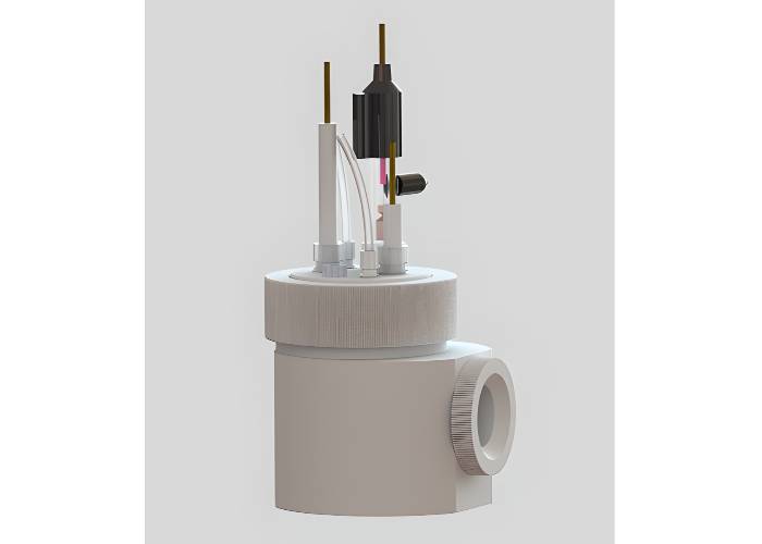
Sealed cells close the headspace so gas can be swept with an inert purge, collected for gas chromatography, or kept isolated from ambient oxygen during long chronoamperometry runs. The Photoelectrochemical Cell – Sealed Type and the PTFE bodied Photoelectrochemical Cell, sealed PTFE cell both use a removable Ø24 mm quartz window with either a glass or PTFE housing. The PTFE version is worth specifying whenever the electrolyte contains halides, is strongly acidic or basic, or is likely to attack borosilicate over an extended experiment. PTFE offers very high chemical resistance to most common aqueous and non-aqueous PEC electrolytes, at the cost of an opaque body (light enters only through the quartz window, which is not a limitation for standard front illuminated or back illuminated single compartment work).
Jacketed cells
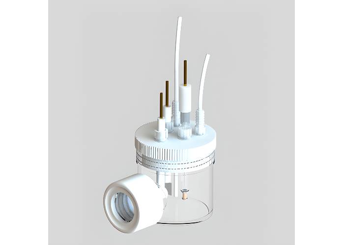
Jacketed cells add a second concentric wall through which water or a coolant is circulated from a recirculating bath, giving direct control over electrolyte temperature. This matters more than it might first appear. A study from Brookhaven National Laboratory’s Center for Functional Nanomaterials found that raising the electrolyte temperature increased the photocurrent of a bismuth vanadate photoanode for solar water splitting by around 40%, attributing the gain to more efficient charge carrier separation and a favourable surface reconstruction at the electrode. Separate work on silicon doped haematite has tracked photoelectrode performance systematically from 25°C to 65°C using standard three electrode chronoamperometry, and modelling of tandem PEC water splitting systems has shown that electrolyte ionic conductivity itself increases measurably with temperature over the 20–80°C range typically encountered under solar simulator illumination. An unthermostatted cell under prolonged illumination can experience electrolyte-temperature drift, so apparent changes in photocurrent may contain both material and thermal contributions.
The Jacketed Photoelectrochemical Cell – Sealed Type and the Jacketed Photoelectrochemical Cell – Unsealed Type both use the same removable Ø24 mm quartz window as the non jacketed range, so switching to temperature control does not cost you optical access. Consider a jacketed cell for long-duration or temperature-sensitive measurements whenever illumination causes measurable electrolyte-temperature drift. The need depends on light-source heat load, cell volume, ambient conditions and the required measurement precision.
4. Single compartment versus H-type: when the anode and cathode need separating
A single compartment cell puts the working, counter, and reference electrodes in one shared electrolyte volume. It is simpler to assemble, cheaper, and perfectly adequate whenever cross contamination between anode and cathode products is not a concern. Most routine linear sweep voltammetry, Mott–Schottky measurements, and short photostability screens fall into this category.
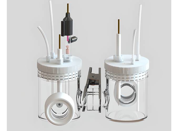
H-type (dual compartment) cells physically separate the working and counter electrode environments with an ion exchange membrane, connected through a narrow bridge or frit. This separation earns its complexity in three situations:
- Gas product studies, where hydrogen from a photocathode and oxygen from a counter electrode need to stay apart to avoid recombination, explosive gas mixtures, or contaminated gas chromatography samples.
- CO₂ reduction, where anodic oxidation products (typically oxygen, but sometimes organic oxidation by products from the sacrificial electrolyte) must not reach the cathode compartment and skew product selectivity.
- Photocorrosion studies, where dissolved species released at one electrode could plate out on, or otherwise contaminate, the other.
ScienceGears offers three H-type PEC configurations, each suited to a different level of complexity:
- The H-Type Membrane Double Channel Photoelectrochemical Cell gives both chambers their own Ø24 mm quartz window, so anode and cathode can each be illuminated independently or simultaneously, which is useful for tandem or bias free PEC configurations where both electrodes are photoactive.
- The H-Type Membrane Single Channel Photoelectrochemical Cell – Sealed Type keeps a single optical channel on the working side, which simplifies alignment when only the working electrode is photoactive and the counter electrode does not need illumination.
- The H-Type Jacketed Photoelectrochemical Cell – Sealed Type combines the dual chamber separation with temperature control, and the H-Type Jacketed Photoelectrochemical Cell, 3-Port adds a dedicated third port for a reference electrode or a gas sampling line without disturbing the working or counter electrode positions once they are aligned, allowing the reference electrode or sampling line to remain fixed between runs.
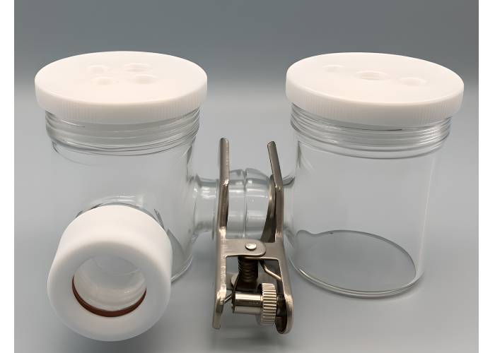
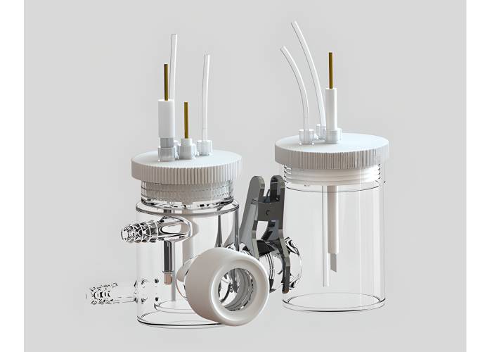
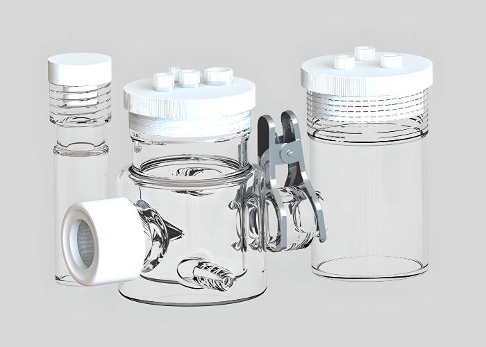
For gas fed CO₂ reduction specifically, where the working electrode is a gas diffusion electrode (GDE) rather than a conventional immersed photoelectrode, the purpose built Photoelectrochemical CO₂ Reduction Flow Cell with Quartz Window goes a step further: CO₂ is delivered through a flow field directly to the gas side of the GDE, forming a three phase gas–catalyst–electrolyte interface, while the counter electrode sits in a physically separate compartment on the anode side to keep oxidation products from interfering with CO₂ reduction product analysis. This is a different cell architecture from the glass H-type range above and suits catalyst coated carbon papers, PTFE treated gas diffusion layers, and MEA style assemblies rather than immersed semiconductor wafers.

5. Illumination geometry: front side, back side, and multi window designs
Where the light hits the photoelectrode is not a matter of convenience. It changes what you are physically measuring.
Front side illumination, where light strikes the semiconductor–electrolyte junction directly, is the default for most immersed photoelectrode work, and it is what a standard single window cell delivers. It is appropriate whenever the photoactive layer is thick relative to the light absorption depth, or whenever the substrate underneath the film is opaque (a metal foil or another opaque conductive substrate), because there is no other option.
Back-side illumination is used in several photoelectrode transport and optical studies, including measurements designed to determine minority-carrier diffusion length. Published methodology in this area illuminates a wedge shaped, graded thickness semiconductor film from the back through a transparent ohmic contact and collects the resulting front side photocurrent at the liquid junction; the way photocurrent falls off as the absorber gets thicker gives the diffusion length directly, without needing to know the material's absorption coefficient or doping level independently. This technique has been demonstrated on sputtered tungsten trioxide and polished bismuth vanadate films in contact with aqueous electrolyte. Both are common PEC photoanode materials. The practical implication for cell selection: if your goal is characterising an absorber's transport properties rather than just measuring its photocurrent, you need optical access to the back of the electrode, which single window cells cannot provide unless the electrode itself is repositioned or the illumination source is moved to the opposite side.
Multi window cells solve this without re mounting the electrode between measurements. The all quartz Photoelectrochemical Cell (Quartz), with four optically transparent faces, lets a fixed electrode be illuminated from any side simply by repositioning the light source or the cell on the bench. This is genuinely useful for comparing front illuminated versus back illuminated photocurrent on the same electrode in the same session, which removes electrode to electrode variability from the comparison. The double channel H-type cell offers a related but distinct capability: independent illumination of two separated compartments, rather than multiple angles onto a single compartment.
A practical note on illumination intensity and area. Standard PEC practice benchmarks photocurrent against a solar simulator calibrated to 1 sun (AM1.5G, 100 mW cm⁻², or equivalently 1 kW m⁻²), and most bench scale PEC cells define a fixed illuminated working electrode area (defined by the optical aperture and electrode holder for the specific setup) set by the window diameter and the electrode clamp or holder used. Keeping the illuminated area consistent between electrodes and between cells is what makes photocurrent densities (mA cm⁻²) from different sessions genuinely comparable; a cell swap that changes the effective illuminated area without you noticing is a common, avoidable source of apparent “batch to batch” catalyst variability. ScienceGears’ electrode clamp and holder range is designed to keep this area consistent across the PEC cell range.
6. Reference electrode placement and uncompensated resistance
The reference electrode's job is to hold a stable, known potential so that changes in the working electrode's potential can be attributed to the working electrode and not to drift in the reference. Where it physically sits in the cell has a direct, quantifiable effect on data quality through uncompensated resistance (often written Ru or Rs).
When current flows between the working and counter electrodes, the electrolyte between them develops a potential gradient. The reference electrode measures whatever potential exists at its own physical location within that gradient, not the potential at the working electrode surface itself. The difference between the two is the ohmic (or “iR”) drop, equal to the current multiplied by the uncompensated resistance between the reference sensing point and the working electrode. The further the reference sits from the working electrode, or the less conductive the electrolyte, the larger this error becomes, and photoelectrochemical measurements are particularly exposed to it because photocurrents on illuminated semiconductors can be substantial relative to the modest conductivity of many PEC electrolytes.
The standard fix is a Luggin capillary, a fine electrolyte filled tube that carries the reference electrode's sensing tip close to the working electrode surface without physically touching it. Positioning it correctly is a genuine trade off, not a “closer is always better” rule: bringing the capillary tip too close to the working electrode creates a shielding effect that distorts the local current distribution, because the capillary itself blocks part of the electrode surface from normal ion flux. Established practice for the closest safe placement of a Luggin capillary is roughly two tip diameters (2d) from the working electrode surface. Closer than that risks measurable shielding error, while positioning much further away reintroduces the uncompensated resistance the capillary was meant to eliminate. The Luggin tip should not contact or physically obstruct the working electrode. Moving the reference sensing point closer reduces the uncompensated solution resistance, but excessively close placement can distort the current distribution through shielding.
This is precisely the design consideration built into ScienceGears’ Photoelectrochemical CO₂ Reduction Flow Cell with Quartz Window: the reference electrode sits in the main electrolyte compartment close to the working region specifically to keep uncompensated resistance low, while the counter electrode is isolated in a separate compartment on the anode side, which separates “keep the reference close for accurate potential control” from “keep the counter electrode far enough away, and physically isolated, to stop its products interfering with the reaction under study.” The H-Type Jacketed Photoelectrochemical Cell, 3-Port addresses the same problem from the hardware side, by giving the reference electrode a dedicated port independent of the working and counter electrode ports, so its position can be fixed once and does not need to be disturbed between runs.
7. Cell volume and electrode geometry
Cell volume is often treated as an afterthought, but it interacts with both electrolyte cost and thermal stability.
ScienceGears’ PEC range is available across the same core volumes (50 mL, 100 mL, and 150 mL) on nearly every single compartment, jacketed, and H-type configuration, with the H-Type Membrane Single Channel Photoelectrochemical Cell additionally available at 250 mL for larger scale or longer duration work.
Smaller volumes (50 mL) minimise the amount of electrolyte and, where relevant, precious metal catalyst needed per run, which is a meaningful saving across a screening campaign testing dozens of candidate photoelectrodes. The trade off is thermal mass: a smaller electrolyte volume heats up faster under continuous solar simulator illumination and is more sensitive to small changes in ambient temperature, which strengthens the case for pairing a 50 mL cell with a jacketed configuration if runs extend beyond a few tens of minutes.
Larger volumes (150–250 mL) can reduce bulk electrolyte composition and pH drift during long electrolysis runs, although local concentration polarisation still depends on mass transport at the electrode. Larger volumes also give the electrolyte enough thermal mass that short term illumination changes have a smaller relative effect on temperature. They also make sense whenever the experiment needs to withdraw electrolyte aliquots for product analysis over the course of a run without materially changing the reaction volume.
Electrode geometry compounds this. Most ScienceGears PEC cells accept L shaped working electrodes or standard electrode clamps, and the illuminated area is set by the window diameter (typically Ø24 mm) in combination with the clamp aperture. Keep the electrode to window distance and the clamp aperture fixed across a comparison series; changing either between electrodes can alter the illuminated area and, depending on the optical geometry, the irradiance reaching the semiconductor surface, independent of any change in the catalyst itself.
8. Decision matrix: matching your experiment to a cell
| Application | Recommended cell type | Specific product | Key rationale | Key constraint |
|---|---|---|---|---|
| Routine photoanode/photocathode screening at ambient temperature | Single compartment, sealed | Photoelectrochemical Cell – Sealed Type | Simple three electrode setup with a replaceable quartz window | No active temperature control |
| UV action-spectrum or IPCE measurements requiring wavelengths significantly attenuated by borosilicate glass | All quartz, four sided illumination | Photoelectrochemical Cell (Quartz) | No borosilicate body to contribute stray UV absorbance | Higher cost; fixed cube geometry |
| Fast electrode swaps, method development, teaching demonstrations | Single compartment, unsealed | Photoelectrochemical Cell – Unsealed Type | Open top access for rapid electrode changes | Not gas tight; unsuitable for gas product quantification |
| Halide, strongly acidic, or strongly basic electrolytes | Sealed, PTFE body | Photoelectrochemical Cell, sealed PTFE cell | PTFE resists attack from aggressive electrolytes | Opaque body; illumination only through the quartz window |
| Multi hour photostability run requiring stable temperature | Jacketed, sealed, single compartment | Jacketed Photoelectrochemical Cell – Sealed Type | Water/coolant jacket removes thermal drift from long runs | Larger footprint; needs a recirculating bath |
| Rapid thermal screening with frequent electrode access | Jacketed, unsealed | Jacketed Photoelectrochemical Cell – Unsealed Type | Combines temperature control with open top access | Not gas tight |
| HER/OER with separated gas products, temperature controlled | H-type, jacketed, sealed | H-Type Jacketed Photoelectrochemical Cell – Sealed Type | Membrane separated chambers plus thermal stability | Two windows to align; longer set up time |
| CO₂ reduction needing a dedicated reference or gas sampling port | H-type, jacketed, 3-port | H-Type Jacketed Photoelectrochemical Cell, 3-Port | Extra port keeps the reference/sampling line fixed between runs | Bulkier glassware assembly |
| Membrane separated PEC, only the working side is photoactive | H-type, single optical channel, sealed | H-Type Membrane Single Channel PEC Cell | One optical channel keeps alignment simple | Counter electrode side still needs its own access |
| Tandem or bias free configurations with two photoactive electrodes | H-type, double optical channel | H-Type Membrane Double Channel PEC Cell | Both chambers independently illuminable | Needs two aligned light sources for simultaneous use |
| Gas fed CO₂ reduction on a GDE or MEA style photocathode | PEC CO₂ reduction flow cell | Photoelectrochemical CO₂ Reduction Flow Cell with Quartz Window | Gas fed flow field forms a stable three phase interface, isolated counter compartment | Requires GDE fabrication and flow field hardware |
| Small volume, precious catalyst screening series | Any 50 mL sealed or PTFE variant | Photoelectrochemical Cell – Sealed Type (50 mL) | Minimises electrolyte and catalyst consumption per run | Lower thermal mass; temperature drifts faster without a jacket |
| Long duration run with periodic electrolyte sampling | Any 250 mL single channel H-type | H-Type Membrane Single Channel PEC Cell (250 mL) | Larger reservoir tolerates aliquot withdrawal without materially changing reaction volume | Larger electrolyte and catalyst loading requirement |
9. FAQ
What is the real difference between a quartz window cell and an all quartz cell?
Both give you a Ø24 mm (or similar) optically clear window for illumination. The difference is the body: a quartz window cell is built from borosilicate glass or PTFE with only the window itself made of quartz, which is fine for visible light work. An all quartz cell has no borosilicate anywhere in the light path, which matters specifically for deep UV measurements, where a borosilicate body can otherwise contribute stray absorbance even when the working window is quartz.
Do I need a jacketed cell for room temperature PEC measurements?
Not for short measurements. A few minutes of linear sweep voltammetry will not meaningfully change the electrolyte temperature. For longer or temperature-sensitive measurements, monitor the electrolyte temperature. If illumination produces meaningful temperature drift, a jacketed cell provides controlled thermal conditions and improves comparability between runs.
When should I choose an H-type cell over a single compartment cell?
Choose H-type whenever anode and cathode products need to stay apart: quantitative gas product analysis (H₂/O₂ or CO₂ reduction products), photocorrosion studies where dissolved species from one electrode could contaminate the other, or any experiment where counter electrode by products would skew your interpretation of working electrode selectivity. If none of that applies, a single compartment cell is simpler to assemble and easier to align.
Where should the reference electrode sit relative to the photoelectrode?
As close as practical without touching or shielding the working electrode. Commonly cited practice places a Luggin capillary tip no closer than roughly two tip diameters from the working electrode surface. Closer risks blocking part of the electrode surface and distorting current distribution; further away increases uncompensated resistance and the associated iR error in your measured potentials.
Should I illuminate my photoelectrode from the front or through the back?
Front side illumination (light hitting the semiconductor–electrolyte junction directly) is the default for most photocurrent measurements and is what standard single window cells provide. Back side illumination, through a transparent substrate, is a deliberate technique used to determine minority carrier diffusion length from graded thickness absorber films, and requires optical access to the electrode's rear face. That means either a dedicated back illumination set up or a multi window cell that lets you reposition the light source without re mounting the electrode.
What cell volume should I choose for a screening study versus a long duration test?
Smaller volumes (50 mL) minimise electrolyte and catalyst consumption across a multi electrode screening series but have less thermal buffering, so pair them with a jacketed configuration for anything beyond short measurements. Larger volumes (150–250 mL) give better thermal stability and tolerate periodic electrolyte sampling for product analysis without materially diluting the reaction, making them a better fit for single long duration stability or selectivity runs.
10. Expert support: how ScienceGears works alongside your research
ScienceGears was founded by a PhD trained electrochemist with hands on research experience in photoelectrochemical cell design, semiconductor photoelectrode characterisation, and the practical, bench level problems that come with pairing illumination hardware to electrochemical measurements. We understand the difference a Luggin capillary position or a window material choice makes to your data, because we have had to troubleshoot exactly those problems ourselves.
Cell geometry consultation
Send us your photoelectrode material, band gap, electrolyte, and the measurement you are trying to make (photocurrent screening, IPCE spectrum, minority carrier diffusion length, gas product quantification), and our technical team will recommend a window material, containment, and compartment configuration before you commit to an order. Talk to our technical team →
Illumination and reference electrode troubleshooting
If your photocurrent data looks noisy, drifts under continuous illumination, or does not reproduce between cells, we can help diagnose whether the cause is uncompensated resistance, illuminated area inconsistency, or thermal drift, and recommend the specific hardware change that fixes it.
Complete system supply
- Photoelectrochemical Cells range
- Reference electrodes
- Counter electrodes
- Electrode clamp and holder
- Working electrodes
- H-Cell range
- In-situ and operando electrochemical cells
Local AU/NZ stock with same day dispatch
ScienceGears holds core photoelectrochemical cell configurations and electrode accessories in local stock across Australia and New Zealand, with same day dispatch on in stock items so a cell geometry change does not have to mean weeks of downtime waiting on an overseas shipment.
“Cell geometry is part of the measurement, not merely the container. Controlling the window material, compartment configuration and reference-electrode position can substantially improve measurement reproducibility.”
11. Further reading
- H-Cell Electrochemical Reactors: Dual-Chamber Systems Guide
- Photoelectrochemical Cells range overview
- In-Situ & Operando Electrochemical Cells
- Reference electrodes
- H-Cell range
12. Get in touch
Not sure which configuration fits your experiment? Tell us your photoelectrode material, target reaction, and electrolyte, and we will recommend a cell and send a tailored quote within one business day.
Request a quote Contact our technical team