


In this guide: You will find a complete, practical compatibility reference for connecting MicruX thick-film screen-printed electrodes and thin-film microfabricated electrodes—and, where compatibility has been verified, iGii/Gii-Sens electrodes—to compatible laboratory potentiostats — covering the connector and adaptor options discussed in this guide, the banana plug and contact pad conventions that govern compatibility, the four-pin versus three-pin distinction that catches most new SPE users by surprise, and a step-by-step setup sequence for both microvolume drop-cell and full-immersion measurement modes.
Table of contents
- The connection problem that wastes a researcher's first hour with SPEs
- Understanding the SPE contact pad format
- MicruX thick-film SPE connectors — the full range
- iGii and graphene SPE connectors
- Thin-film microfabricated electrode connectors
- Connecting SPEs to your potentiostat — practical setup
- Microvolume drop-cell vs full-immersion — choosing the right mode
- Extending the platform — external reference and counter electrodes
- Common connection problems diagnosed
- Frequently asked questions
- Expert support — how ScienceGears works alongside your research
1. The connection problem that wastes a researcher's first hour with SPEs
Screen-printed electrodes arrive in the lab looking deceptively simple — a flat strip of ceramic or PET with printed conductive tracks, an integrated electrode configuration, often incorporating working, reference and auxiliary/counter electrodes. The problem begins the moment you reach for a cable to connect them to the potentiostat already sitting on your bench.
Many laboratory potentiostats provide electrode leads or sockets using 2 mm or 4 mm banana connections, although proprietary and instrument-specific cable formats are also common. SPEs terminate in flat contact pads whose pitch, number, order and dimensions vary between manufacturers and electrode formats — flat, exposed, and not immediately obvious how to interface with anything. The first connection attempt typically involves improvisation: crocodile clips pressed onto the pad edges, copper tape strips bridging to banana sockets, or simply abandoning the SPE in favour of a conventional electrode setup the researcher already knows how to connect.
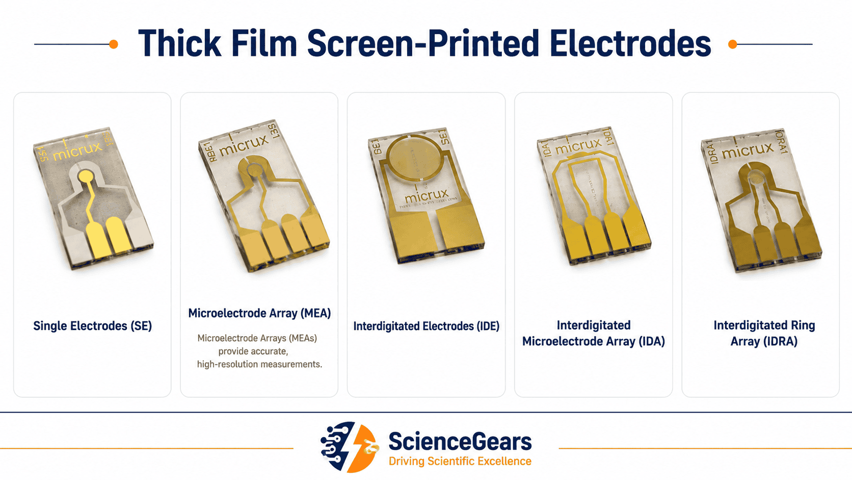
None of these workarounds are necessary. Various accessories are available for the quick and easy interconnection of screen-printed electrodes with analytical instrumentation — but the range is wider and more nuanced than most researchers realise when they first encounter it, and the choice between them depends on which SPE format you have, which potentiostat you are using, and whether you are working in microvolume drop-cell mode or full immersion.
This guide works through the relevant MicruX connector and adaptor options for thick-film SPEs and thin-film microfabricated electrodes, together with the checks required before connecting other sensor formats — in enough practical detail to get a working connection on any laboratory potentiostat without improvisation.
2. Understanding the SPE contact pad format
Before selecting a connector or adaptor, you need to understand the physical format of your specific SPE's contact pads — because the most common SPE compatibility issue is not a missing adaptor but a mismatch between the electrode's contact pad layout and the connector's input geometry.
2.1 The standard 2.54 mm pitch
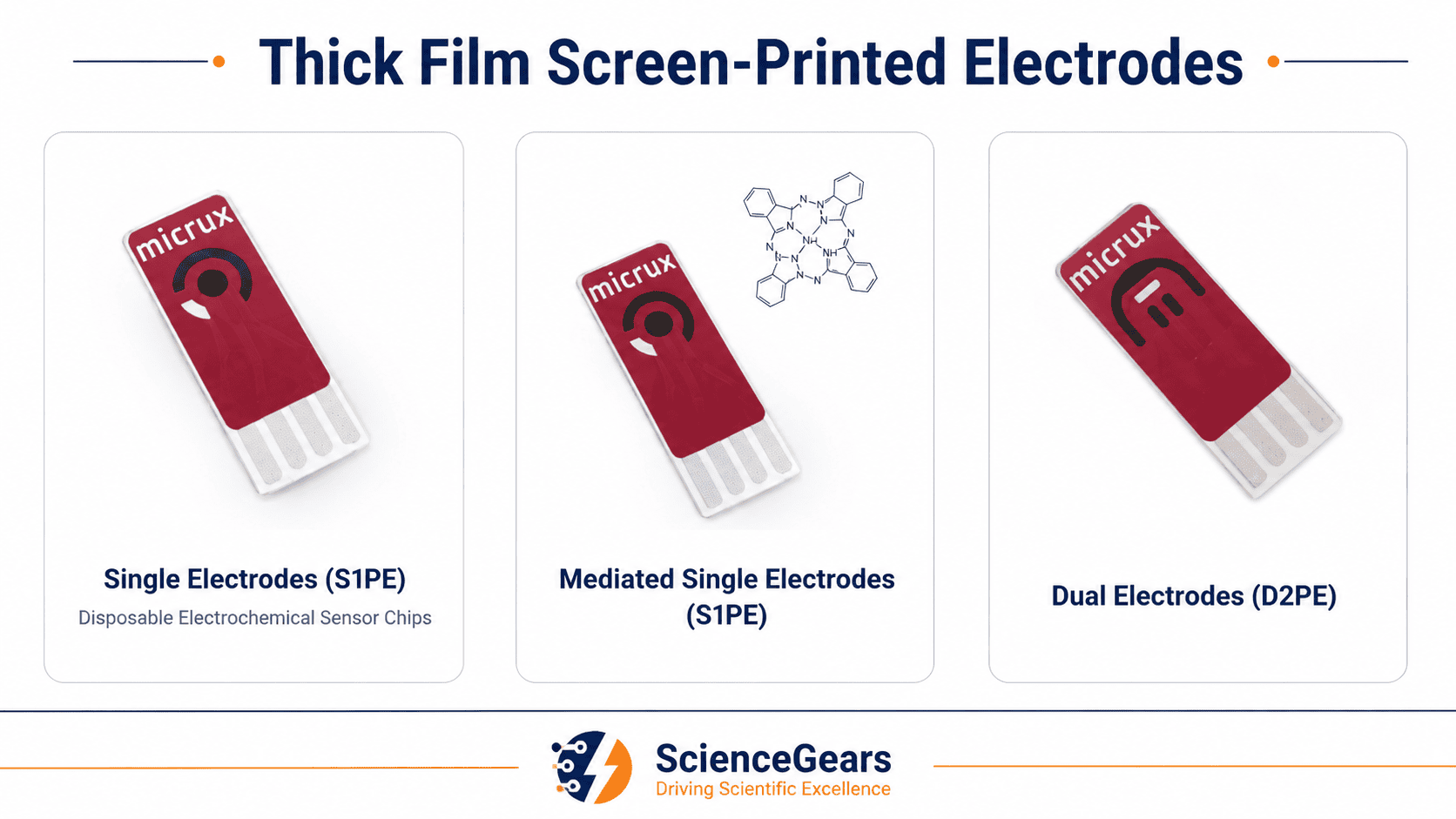
MicruX S1PE and D2PE electrodes use a four-contact-pad format. Connector compatibility depends on the complete mechanical and electrical geometry—not only the apparent pin spacing. Before inserting an electrode into a third-party connector, verify the pad pitch, pad count, strip dimensions, insertion depth and pad assignment against the current electrode and connector documentation.
Compare the available single- and dual-working-electrode formats, electrode materials and substrate options on the Thick-Film Screen-Printed Electrodes page.
2.2 The four-pad versus three-pad distinction
The SPE-ADAPTOR is intended to interface compatible 3-pin third-party SPE connectors with MicruX S1PE electrodes, which use four contact pads.
This is the most important compatibility distinction in this guide. MicruX S1PE and D2PE electrodes both present four contact pads, but the pad functions differ. On S1PE electrodes, the two working-electrode contact pads are electrically common, alongside the reference-electrode and auxiliary-electrode pads. On D2PE electrodes, the four pads provide separate connections for WE1, RE, WE2 and AE. The fourth pad is therefore not a generic guard connection. Always use the pad assignment for the exact electrode model.
Review the connector options available for MicruX four-pad screen-printed electrodes on the SPE Connectors page.
For compatible S1PE applications, the SPE-ADAPTOR may allow an existing 3-pin third-party connector to be used with the MicruX four-pad S1PE format. It should not be presented as a means of operating a D2PE electrode with independent WE1 and WE2 control.
2.3 Ceramic versus PET substrates — handling implication
MicruX S1PE electrodes are available on PET or ceramic substrates, depending on the selected model. Handle the strip by its edges, avoid flexing a ceramic substrate, insert it straight into the connector and do not force it if resistance is encountered. Follow the current manufacturer handling instructions for the specific electrode and connector.
3. MicruX thick-film SPE connectors — the full range
ScienceGears supplies the complete MicruX connector range for thick-film S1PE and D2PE electrodes. There are three distinct products, each solving a different setup requirement.
3.1 SPE-CABLE — the universal flexible connection
The SPE-CABLE is a screen-printed electrode connector for interfacing the printed electrodes with any potentiostat, enabling the use of microvolumes (sample drops of 20–50 µL) or immersion in the solution. The cable is compatible with S1PE and D2PE screen-printed electrodes and is available with two terminal options: 2-mm female banana plugs (includes male adapter) or 2-mm male banana plugs (includes crocodile clips).
The SPE-CABLE is the starting point for most researchers connecting MicruX SPEs to a general-purpose laboratory potentiostat. The electrode end clips onto the SPE's four contact pads; the potentiostat end terminates in 2 mm banana plugs. The instrument end uses 2 mm banana connectors. Direct compatibility therefore depends on the connector size and gender provided by the potentiostat or its electrode cable; a suitable verified adaptor may be required.
Which terminal option to choose:
- 2 mm female banana connectors, with male adaptors included: connect directly to compatible 2 mm male instrument leads. Use the supplied male adaptors where the instrument presents compatible 2 mm female sockets.
- 2 mm male banana connectors, with crocodile clips included: connect directly to compatible 2 mm female sockets. Use the crocodile clips only with suitable exposed terminals or instrument lead ends. For a 4 mm socket, use an appropriate 2 mm-to-4 mm adaptor rather than attempting to clip into the socket.
Using SPE-CABLE in microvolume mode: Drop 20–50 µL of sample directly onto the printed electrode surface with the electrode lying flat and the cable connected. Support the electrode on a clean, stable and level surface during drop-cell measurements. Ensure that the sample covers all required active electrode areas without reaching the contact-pad region.
Using SPE-CABLE in immersion mode: The cable is designed so that the electrode end can be submerged in solution whilst the electrical connections remain dry. This is appropriate for experiments where the sample volume is large enough to immerse the electrode or where a flow cell is being used. Ensure only the printed electrode area is submerged — the connector contact region should remain above the solution level.
3.2 SPE-BOX — the enclosed drop-cell connector
The SPE-BOX is a small box connector for screen-printed electrodes that acts as an interface between the printed electrodes and any available potentiostat in the laboratory. It allows the use of microvolumes (sample drops of 20–50 µL). The connector is compatible with S1PE and D2PE screen-printed electrodes.
The SPE-BOX differs from the SPE-CABLE in form factor rather than fundamental compatibility — it encloses the SPE within a small housing rather than holding it at the end of a flexible cable. This makes the SPE-BOX more practical when the electrode needs to sit stably on a bench surface without the risk of tipping or flexing during a measurement. It is particularly useful in teaching laboratory environments, in automated sampling workflows where the electrode position must be reproducible, and in situations where the SPE is being used with a pipette-dispensed sample where a flat, stable surface is needed beneath the electrode.
The SPE-BOX is supplied with 2 mm female banana connections. Confirm the size and gender of the potentiostat interface and use a suitable adaptor where required.
3.3 SPE-ADAPTOR — bridging 3-pin connectors to 4-pad MicruX SPEs
The SPE-ADAPTOR is designed for 3-pin SPE connectors from other brands to interface MicruX screen-printed electrodes. This versatile and cost-effective solution enables the use of MicruX screen-printed electrodes with various commercial connectors.
The SPE-ADAPTOR is an option when you already have a compatible 3-pin SPE connector and want to use a MicruX S1PE electrode. Verify the third-party connector geometry and pin assignment before use.
Browse the full MicruX SPE connector range →
4. iGii and graphene SPE connectors
Current iGii product terminology uses Gii-Sens for its ready-to-use 3D carbon nanomaterial electrodes. Connector compatibility is specific to the supplied electrode variant. Before recommending a MicruX SPE-CABLE, SPE-BOX, thin-film cable or SPE-ADAPTOR, verify the electrode dimensions, pad count, pad pitch and pad order using the current iGii datasheet or a physical sample. Do not claim direct compatibility with MicruX hardware unless the exact combination has been documented or tested.
5. Thin-film microfabricated electrode connectors
MicruX thin-film microfabricated electrodes use a dedicated connector and platform family that is distinct from the thick-film S1PE and D2PE connector format. Do not classify iGii electrodes as MicruX thin-film microfabricated electrodes unless the supplier documentation explicitly identifies them that way.
5.1 Thin-film electrode cables and platform interfaces
Individual MicruX thin-film electrodes use the dedicated TF-CABLE, while two-contact interdigitated electrodes use the IDE-CABLE. Both connector types terminate in instrument-side banana connections. IDC cables and miniUSB breakout boxes are used with particular multiplexed platforms; they are not the standard interface for every thin-film electrode.
The configuration supplied with two miniUSB boxes and two IDC connectors is the MicruX Multi-electrode Chip Platform, not the standard Drop-Cell Connector. Keep these two product descriptions separate.
5.2 AIO and AIO-SPE platform compatibility
The MicruX AIO platform is designed for thin-film electrodes and uses its dedicated universal platform cable. The AIO-SPE platform is the corresponding platform for MicruX thick-film SPEs and is supplied with or compatible with the SPE-CABLE. Do not describe the AIO-SPE platform as using the same IDC interface as the multiplexed thin-film platforms.
6. Connecting SPEs to your potentiostat — practical setup
6.1 The standard three-electrode assignment
Lead count and assignment depend on the electrode and connector. A conventional S1PE measurement uses WE, RE and AE/CE; D2PE adds a separate WE2 connection; and an interdigitated two-contact electrode may use only two terminals. Follow the labels and pinout supplied for the exact electrode and cable.
|
Lead |
Connected to |
Function |
|
Working electrode (WE) — green |
SPE working electrode pad |
Redox reaction occurs here; current is measured here |
|
Reference electrode (RE) — white or blue |
SPE reference electrode pad |
Provides the potential reference; the potentiostat draws only negligible current through its high-impedance input |
|
Counter / auxiliary electrode (CE/AE) — red |
SPE counter electrode pad |
Completes the circuit; carries the return current |
Connect each lead to the corresponding input socket on your potentiostat's front panel. Do not rely on colour alone. Confirm each lead using the labels and pinout supplied with the connector and potentiostat, because colour conventions vary between instruments and cable systems. but verify against your potentiostat's labelling — some instruments label the counter electrode as the "auxiliary" electrode, which is the same terminal by a different name.
6.2 Connecting to research-grade potentiostats with banana sockets
Match each labelled electrode lead to the corresponding potentiostat terminal, while also checking connector size and gender. Where both sides use compatible 2 mm connectors, connect them directly. Where the instrument uses 4 mm sockets or a proprietary cable, use the appropriate adaptor or connect to the labelled instrument electrode leads according to the instrument manual. Do not attach a crocodile clip directly into a banana socket.
6.3 Connecting to the MicruX ECStat and ECSens instruments
The MicruX ECSens is designed specifically for screen-printed electrodes, making it ideal for standard and custom sensor experiments, and includes all necessary cables, connectors, and software for hassle-free interfacing and operation out of the box.
The MicruX ECStat is compatible with screen-printed electrodes, thin-film electrodes, and common electrochemical platforms.
With the MicruX ECSens, S1PE and D2PE electrodes connect through the sensor interface supplied with the instrument package. The ECStat standard package instead includes a general sensor cable with 2 mm banana connectors and alligator/crocodile clips. A suitable SPE-CABLE, SPE-BOX or other appropriate platform interface is therefore required for an SPE unless an SPE-specific accessory has been ordered separately.
6.4 Bipotentiostat mode — dual working electrode connection
For experiments requiring two independent working electrode potentials — generator-collector studies, dual-analyte detection, or differential sensing on a D2PE dual-working-electrode SPE — a bipotentiostat is required. The D2PE dual-electrode SPE provides two physically separated working electrode pads alongside a shared reference and counter electrode. In this configuration:
- WE1 connects to the bipotentiostat's first working electrode input
- WE2 connects to the bipotentiostat's second working electrode input
- RE and CE connect normally to the single reference and counter electrode inputs
The ECSens supports both standard and BIPOT modes for advanced investigative flexibility, with a potential range of ±1.5 V, selectable current ranges from 0.25 µA to 12.5 mA and a stated maximum current of ±5 mA, according to the current manufacturer specification.
Independent control of WE1 and WE2 requires a compatible bipotentiostat and a correctly mapped four-lead connection. Browse the full Potentiostats and Galvanostats range.
7. Microvolume drop-cell vs full-immersion — choosing the right mode
The physical connection is the same in both modes — what changes is the sample presentation to the electrode and the volume required.
7.1 Microvolume drop-cell mode (20–50 µL)
Lay the SPE flat on the bench with the printed electrode surface facing upward. Apply 20–50 µL of sample solution directly onto the electrode surface using a micropipette, ensuring the droplet bridges all three electrode areas (working, reference, and counter) without spilling over the contact pads at the electrode's tail end. The droplet acts as its own electrolyte volume and cell body simultaneously — this is the operating principle that makes SPE drop-cell testing so practical for biosensor development and point-of-care applications.
Key considerations in drop-cell mode:
- Ensure the droplet fully covers the working electrode area — a partial droplet that does not contact the reference or counter electrode will produce an open-circuit error or an invalid measurement with no stable reference potential
- Evaporation can change analyte concentration and electrolyte composition during a measurement. The rate depends on droplet geometry, temperature, airflow and humidity. Minimise exposure time and use an appropriate cover or controlled environment where required.
- For volumes below the manufacturer's recommended range, confirm that every required active electrode area remains fully wetted. Otherwise, use the recommended volume or a platform designed for a smaller sample volume.
7.2 Full-immersion mode
Submerge only the printed electrode area of the SPE in the analyte solution whilst keeping the contact pad tail dry. The SPE-CABLE's geometry is designed to allow this — the electrode end is submerged and position the electrode so that only the intended active region is immersed and the connector and contact pads remain dry. Use a small vessel (beaker, vial, or electrochemical cell) that provides enough solution volume to cover the full electrode area without rising to the contact pad region.
Full-immersion is appropriate when: the experiment runs longer than a few minutes and evaporation from a drop would compromise data; when the solution needs stirring or temperature control; or when an external reference or counter electrode is being added to the solution volume alongside the SPE working electrode.
For controlled batch or flow measurements, compare the available Electrochemical and Microfluidic Platforms.
8. Extending the platform — external reference and counter electrodes
Integrated reference and auxiliary/counter electrodes may be suitable for many routine measurements, depending on the electrode materials, electrolyte, expected current and required potential stability. An external reference or counter electrode may be preferable where the printed electrode is incompatible with the chemistry, where drift is observed, or where the current demand exceeds the intended capability of the printed counter electrode.
MicruX offers miniaturised Ag/AgCl reference electrodes and platinum or stainless-steel auxiliary/counter electrodes. Suitability depends on the electrolyte, solvent, potential window, expected current and tolerance for contamination or electrode dissolution. Confirm compatibility with the selected MicruX cell or platform before ordering.
Consider an external reference electrode when a well-defined and stable reference potential is required, when the printed reference is incompatible with the electrolyte or solvent, or when reference drift is evident during long-duration or low-frequency measurements. Select the external reference and filling solution for the specific chemistry. Do not present Ag/AgCl or SCE as universally suitable for all aqueous and non-aqueous systems.
Connection in extended configuration: When using external reference and counter electrodes alongside an SPE working electrode: connect the SPE-CABLE's WE lead to the printed working electrode; connect the RE lead to the external reference electrode; connect the CE lead to the external counter electrode. The printed RE and CE pads on the SPE surface are left unconnected in this configuration — only the printed working electrode is being used from the SPE; the overall experiment remains a three-electrode cell incorporating the external reference and counter electrodes, contributing only its working electrode to the cell.
9. Common connection problems diagnosed
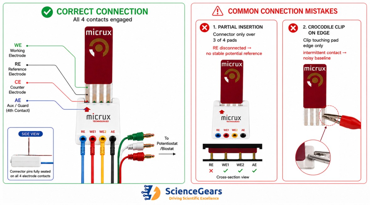
Caption: Correct and incorrect SPE connection examples. Confirm full pad contact, electrode orientation and the model-specific pad assignment before troubleshooting the electrochemical measurement.
|
# |
Symptom |
Most likely cause |
Diagnosis |
Fix |
|
1 |
Open-circuit error on potentiostat startup |
Reference electrode not connected |
Check connector is fully seated — partial insertion may be leaving the RE pad unconnected |
Remove and re-insert connector firmly; verify all four pads are under the connector body |
|
2 |
No current response on CV despite confirmed connection |
Working electrode lead connected to counter pad |
Three-pin connector inserted across wrong three pads on a four-pad SPE |
Use SPE-ADAPTOR to bridge 3-pin connector to 4-pad MicruX format; do not rewire the connector ad hoc; use the specified adaptor or a wiring arrangement verified against the manufacturer pinout |
|
3 |
Highly noisy baseline, unstable current signal |
Intermittent crocodile clip contact on pad edge |
Crocodile clip is on the printed pad's edge rather than its flat surface |
Press crocodile clip flat onto the pad surface; or switch to SPE-CABLE / SPE-BOX for reliable spring-pin contact |
|
4 |
Potential drift during EIS measurement |
Printed Ag pseudo-reference drifting |
Confirm whether the selected SPE uses printed Ag or printed Ag/AgCl and whether that reference is suitable for the electrolyte and required potential scale — drift increases with measurement time and in non-aqueous solvents |
Add an external Ag/AgCl reference electrode to the solution and reassign the RE lead |
|
5 |
Reversed current polarity on CV |
SPE inserted backwards into connector |
WE and CE leads swapped; the connector physically contacts CE pad via the WE input |
Remove SPE, identify the electrode tail orientation marking, re-insert in correct orientation |
|
6 |
Sudden loss of signal mid-experiment |
Connector cable flexed or pulled during measurement |
Physical movement of the SPE-CABLE has disrupted pin contact on a pad |
Secure the cable and SPE against movement during the experiment; use SPE-BOX for vibration-prone setups |
|
7 |
Reference potential reads incorrectly vs expected value |
Droplet not covering RE area |
The 20–50 µL droplet has not bridged all three electrode areas |
Increase droplet volume to fully cover working, reference, and counter printed areas |
|
8 |
CV peak position shifts between nominally identical SPEs |
Contact resistance variation between different electrodes |
Pad surface contamination or variable spring-pin contact pressure |
Do not clean disposable contact pads with solvent unless the electrode manufacturer explicitly permits it. Replace a contaminated disposable strip and inspect the reusable connector contacts.; inspect connector pins for wear |
10. Frequently asked questions
For broader questions about ScienceGears products, ordering, and shipping, visit our main FAQ page.
Q1. Can I use any standard banana plug cable to connect an SPE to my potentiostat, or do I need a dedicated SPE connector?
You cannot use a standard banana plug cable directly — banana plugs terminate in round socket or plug geometry that cannot make reliable contact with the flat, planar contact pads of a screen-printed electrode. The dedicated SPE connector hardware (SPE-CABLE, SPE-BOX) is specifically designed with spring-loaded or clamping contact elements that press onto the flat pad surface with consistent geometry and sufficient contact area to avoid high contact resistance. An improvised connection via crocodile clips pressed on pad edges will produce intermittent contact and a noisy, irreproducible signal.
Q2. My potentiostat has 4 mm banana sockets, not 2 mm. Can I still use MicruX connectors?
Yes, provided the connector size and gender are matched correctly. A 2 mm male cable connector requires a compatible female socket, while a 2 mm female connector requires a male lead or the supplied male adaptor. Where the potentiostat presents 4 mm sockets, use a suitable 2 mm-to-4 mm adaptor or the instrument's labelled electrode cable. Do not attempt to insert or clamp a crocodile clip directly into a banana socket.
Q3. What is the difference between SPE-CABLE and SPE-BOX, and when should I use each?
Both connect MicruX S1PE and D2PE electrodes to any potentiostat with banana plug inputs. The SPE-CABLE holds the electrode at the end of a flexible cable — suitable for immersion experiments or situations where the electrode needs to be positioned freely. The SPE-BOX encloses the electrode in a small housing — better for drop-cell experiments where the electrode needs to sit stably on a flat surface, and for repetitive sample testing where electrode positioning reproducibility matters. In both cases the potentiostat terminal is the same banana plug connection.
Q4. I have a three-banana-plug SPE connector from a previous supplier. Can I use it with MicruX electrodes?
For a compatible MicruX S1PE electrode, use the SPE-ADAPTOR specified for 3-pin third-party connectors. Confirm the connector geometry before use. Do not use a 3-pin interface for full D2PE bipotentiostat operation because WE2 requires its own independent connection.
Q5. Can I connect MicruX SPEs directly to the ECStat or ECSens instruments without an SPE-CABLE?
The ECSens package includes a sensor interface for MicruX S1PE and D2PE electrodes. The ECStat standard package uses a general 2 mm sensor cable rather than a direct four-pad SPE holder, so an SPE-CABLE, SPE-BOX or appropriate platform interface is normally required. Confirm the accessories included in the quoted package before ordering.
Q6. When should I add an external reference electrode instead of relying on the SPE's printed reference?
Use an external reference electrode when the experiment requires a defined reference potential, when the printed reference is unsuitable for the solvent or electrolyte, or when unacceptable drift is observed. Measurement duration alone does not establish a universal cut-off. Select the reference electrode and filling solution for the specific chemical system.
Q7. How can I identify the pad assignment on a MicruX S1PE or D2PE electrode?
Always confirm the pad assignment using the datasheet or connector diagram for the exact electrode model. An S1PE contains one working electrode, one reference electrode and one auxiliary electrode. Its four-pad format includes two electrically common contacts for the same working electrode. A D2PE contains two independent working electrodes, WE1 and WE2, which share the same reference and auxiliary electrodes. The D2PE pads must therefore be connected individually according to the model-specific pinout.
Q8. Do I need a bipotentiostat to use a D2PE electrode?
A bipotentiostat is required when WE1 and WE2 must be controlled independently and measured simultaneously against the shared reference electrode. A conventional single-channel potentiostat may be used with only one correctly connected working electrode at a time, while the other working-electrode contact remains unused.
Q9. How do I match 2 mm male, 2 mm female and 4 mm banana connections?
Match the connector gender on the cable to the opposite gender on the instrument:
Cable termination Instrument connection required
2 mm male plug 2 mm female socket
2 mm female connector 2 mm male lead or supplied male adaptor
2 mm cable to 4 mm socket Suitable 2 mm-to-4 mm adaptor
MicruX cables are available with either 2 mm female connectors, supplied with male adaptors, or 2 mm male plugs, supplied with crocodile clips. Crocodile clips should be used only on suitable exposed terminals or lead ends and should not be inserted or clamped directly into banana sockets.
Q10. Can I replace only the printed reference electrode while retaining the printed counter electrode?
Yes. Connect the external reference electrode to the potentiostat RE lead while retaining the printed working and auxiliary/counter electrodes. Leave the printed reference-electrode contact disconnected. Similarly, only the printed counter electrode may be replaced if required. The selected external electrode must be compatible with the electrolyte, solvent and measurement conditions.
Q11. Can a battery cycler be used to measure a screen-printed electrode?
A conventional battery cycler is normally designed for two-terminal charge–discharge measurements and controls the overall cell current or voltage. A standard screen-printed-electrode experiment generally requires three-electrode control, in which the working-electrode potential is controlled against a reference electrode while current flows through the counter electrode. A potentiostat/galvanostat is therefore normally the appropriate instrument. Some advanced battery cyclers support reference-electrode or three-electrode configurations, but this capability must be confirmed for the specific model.
Q12. What information should I send ScienceGears for a compatibility check?
Please provide:
- Potentiostat or instrument manufacturer and model
- Exact SPE or electrode model
- Clear photographs of the electrode contact pads and instrument cable or sockets
- Connector size and type, such as 2 mm male, 2 mm female or 4 mm
- Intended measurement configuration: drop-cell, immersion, flow-cell or bipotentiostat operation
This information allows the correct connector, cable and adaptor arrangement to be identified before ordering.
11. Expert support — how ScienceGears works alongside your research
Connecting an SPE to a potentiostat is straightforward once the electrode format, pad assignment and instrument-side connector have been confirmed. The reason it sometimes takes much longer is that the connection hardware options are not always explained clearly alongside the electrode itself — what connector format your specific SPE needs, which terminal option matches your potentiostat's banana socket size, and whether the SPE-ADAPTOR is required for your existing connector are all questions that depend on details not visible from a product listing alone.
ScienceGears distributes the complete MicruX SPE and connector range across Australia and New Zealand, and our technical team has hands-on experience connecting MicruX thick-film, iGii graphene sensing strips, and thin-film microfabricated electrodes to the full range of potentiostats we supply and support. When you contact us about an SPE connection question, our technical team can assess the combination using the electrode model, instrument make and model, connector photographs and current product pinouts.
What expert support looks like in practice
Pre-order connection compatibility check If you have an existing potentiostat in the lab and want to confirm which SPE connector is correct for it before ordering — including whether the SPE-ADAPTOR is needed — contact us before purchasing. Please provide the potentiostat make and model, the electrode model, and clear photographs of the instrument cable or socket and electrode contact pads. This normally allows the required interface to be identified accurately.
Complete SPE system supply ScienceGears supplies components across the SPE measurement chain and can confirm compatibility for the exact electrode, connector, platform and potentiostat combination before ordering:
- Thick-film screen-printed electrodes — carbon, graphene, gold, platinum, ceramic, PET
- SPE connectors — SPE-CABLE, SPE-BOX, SPE-ADAPTOR
- Thin-film microfabricated electrodes
- Thin-film connectors — IDC, miniUSB, drop-cell connectors
- 3D Porous Graphene Sensing Strip electrodes
- External electrodes — Ag/AgCl RE, Pt CE, stainless steel CE
- MicruX ECStat — compact bipotentiostat/galvanostat/EIS instrument compatible with SPEs through an appropriate connector or platform interface
- MicruX ECSens — compact sensing bipotentiostat for SPEs
- Potentiostats and galvanostats — full research-grade range
- Electrochemical and microfluidic platforms
Selected accessories may be available from local Australian stock, subject to current inventory and order cut-off times SPE connectors, adaptors, and accessories are held in local Australian inventory.
"The connection between your SPE and your potentiostat is two minutes of work with the right hardware and two hours of frustration without it. We make sure researchers have both the hardware and the guidance." — ScienceGears Technical Team
Further reading
Related ScienceGears resources:
- Thick-film screen-printed electrodes
- SPE connectors
- Thin-film microfabricated electrodes
- Thin-film connectors
- 3D Porous Graphene Sensing Strip electrodes
- MicruX ECStat electrochemical station
- MicruX ECSens compact bipotentiostat
- External electrodes
- Electrochemical and microfluidic platforms
- Potentiostats and galvanostats
- Application notes
Get in touch
Need to confirm which SPE connector is compatible with your specific potentiostat, or unsure whether the SPE-ADAPTOR is required for your setup? Contact our technical team — we aim to respond within one business day.
Request a quote → | Browse disposable sensors → | About ScienceGears →