

In this guide, you will learn how the four main families of ion-exchange membranes differ, how to choose the right Nafion grade for your specific cell format, when to consider an anion exchange or cation exchange membrane, and how to apply an application-by-application decision matrix to your own experimental design.
1 Why Membrane Selection Is More Consequential Than It Appears
You have designed your electrochemical cell, selected your electrolyte, and defined your target reaction. Now you are looking at a membrane catalogue — Nafion 117, Nafion 212, Fumasep FAA-3, Fumasep FKS, bipolar membranes — and the distinctions between them are not immediately obvious.
This is a more consequential decision than most researchers expect.
Choosing the wrong membrane does not simply reduce performance. It can actively invalidate your data. Excessive proton crossover in an H-cell experiment will contaminate your anolyte, distorting Faradaic efficiency calculations. A membrane that swells beyond its rated hydration window will alter your cell’s active area and compression geometry, introducing variability between runs. In alkaline media, using a proton-exchange membrane instead of an anion-exchange membrane can lead to poor ion-transport behaviour, unstable performance, or accelerated degradation depending on the electrolyte, temperature, and operating conditions.
The membrane is not passive hardware. It is a chemically active separator that controls ionic transport, prevents electronic shorting, and when chosen correctly stabilises the electrochemical environment your catalyst needs to perform reproducibly.
This guide walks you through the decision systematically, from membrane families to individual grades to application-specific recommendations. All membranes discussed here are available through ScienceGears’ ion-exchange membrane range, stocked locally for researchers across Australia and New Zealand.
2 The Four Main Ion-Exchange Membrane Families
Ion-exchange membranes are broadly categorised by the type of ion they selectively transport. Understanding these categories first makes every subsequent product decision significantly more straightforward.
2.1 Proton Exchange Membranes (PEM)
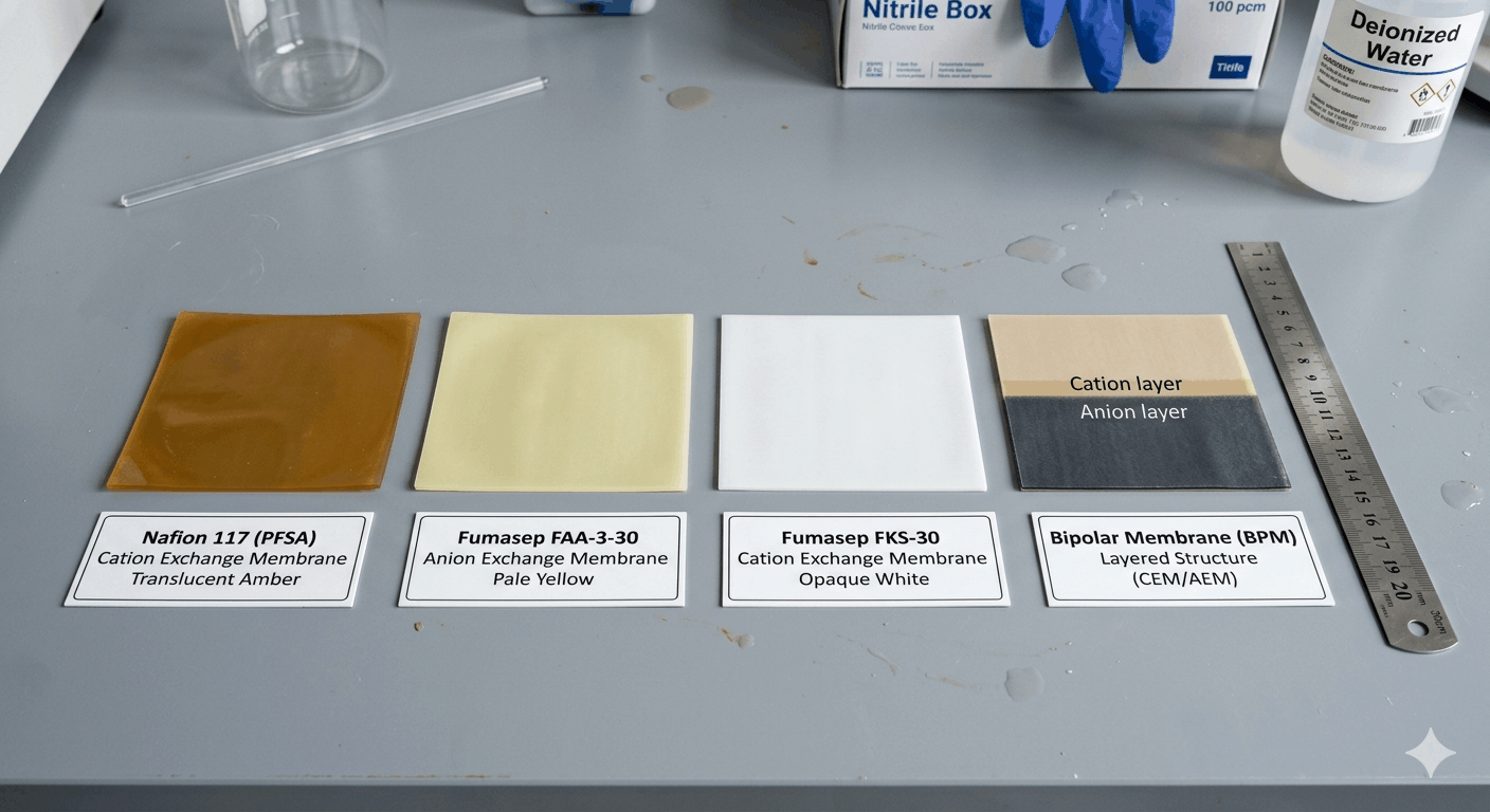
Proton exchange membranes, the most widely used class in electrochemical research, are dense polymer films that conduct hydrogen ions (H⁺) whilst blocking electron transport and preventing bulk liquid mixing between compartments. A widely used commercial example is Nafion™ — a perfluorosulfonic acid (PFSA) membrane, now marketed by Chemours, whose sulphonate groups provide fixed anionic sites that facilitate proton transport.
PEMs are most commonly used in acidic proton-conducting environments. Depending on grade, hydration state, temperature, and test method, Nafion membranes can show high proton conductivity, making them a common choice for PEM fuel cells, PEM water electrolysers, and dual-chamber H-cell experiments.
2.2 Anion Exchange Membranes (AEM)
Anion exchange membranes conduct hydroxide (OH⁻), carbonate (CO₃²⁻), or bicarbonate (HCO₃⁻) ions depending on the electrolyte and operating environment. They carry fixed cationic functional groups — typically quaternary ammonium — that reject cations and facilitate anion transport.
AEMs are the correct choice for alkaline electrochemical systems: AEM water electrolysers (AEMWE), CO₂ electroreduction experiments, and systems designed around earth-abundant, non-platinum catalysts. Fumasep FAA-3 is commonly used in research settings; confirm the exact grade, thickness, and counter-ion form before ordering.
2.3 Cation Exchange Membranes (CEM)
Cation exchange membranes conduct positively charged ions, including H⁺, Na⁺, K⁺, Li⁺, and Ca²⁺, depending on the membrane chemistry and electrolyte. They are commonly used in electrodialysis, ion separation, and selected redox flow battery configurations. Fumasep FKS grades are used as research-grade cation exchange membranes where cation selectivity, membrane resistance, and chemical compatibility are important.
2.4 Bipolar Membranes (BPM)
A bipolar membrane consists of a laminate of cation-exchange and anion-exchange layers joined at a catalytic interface. When operated in reverse bias, this interface catalyses water dissociation, generating H⁺ at the cation side and OH⁻ at the anion side. This behaviour is particularly valuable for pH-gradient electrochemical systems, CO₂ capture and conversion, and two-step electrosynthesis processes where maintaining a fixed pH in each compartment is critical to selectivity.
At-a-Glance Comparison
| Membrane Type | Ion Transported | Typical pH Range | Key Applications |
|---|---|---|---|
| PEM (e.g. Nafion) | H⁺ | Acidic (pH 0–4) | PEM fuel cell, PEMWE, H-cell, MEA |
| AEM (e.g. Fumasep FAA) | OH⁻ / CO₃²⁻ | Alkaline (pH 10–14) | AEMWE, CO₂RR, alkaline electrosynthesis |
| CEM (e.g. Fumasep FKS) | Na⁺, K⁺, Li⁺ | Broad | Electrodialysis, redox flow battery, ion separation |
| Bipolar (BPM) | Generates H⁺ and OH⁻ at the interface under reverse bias | pH-gradient systems | CO₂ conversion, two-step electrosynthesis, pH-split cells |
3 Deep Dive: Nafion Grades Compared — 115, 117, 211, and 212
Nafion is not a single product. Nafion is available in several grades that differ in thickness, manufacturing form, reinforcement, and application suitability. Choosing between them incorrectly can be a significant source of irreproducibility in electrochemical studies.
3.1 Understanding the Naming Convention
For older extrusion-cast Nafion grades such as N115 and N117, the final digit corresponds to nominal dry thickness in mils: N117 is approximately 7 mil and N115 is approximately 5 mil. Solution-cast grades such as NR211 and NR212 are commonly supplied as thinner membranes of approximately 25 µm and 50 µm, respectively. Always verify grade, equivalent weight, ionic form, reinforcement, and dry thickness from the current manufacturer datasheet before ordering.
3.2 Thickness: Dry, Wet, and Hydrated — Why the Distinction Matters
This is the single most frequently searched specification for Nafion membranes and one that product pages rarely answer clearly.
Nafion swells substantially upon hydration, and the degree of swelling affects your cell geometry in ways that matter for reproducibility:
| Grade | Dry Thickness (µm) | Wet Thickness (µm) | Hydrated Thickness (µm) | EW (g mol⁻¹) |
|---|---|---|---|---|
| Nafion 115 | ~127 | ~145 | ~160 | ~1,100 |
| Nafion 117 | ~183 | ~210 | ~230 | ~1,100 |
| Nafion NR211 | ~25 | ~29 | ~32 | ~1,100 |
| Nafion NR212 | ~51 | ~58 | ~64 | ~1,100 |
Wet or hydrated membrane thickness depends on hydration history, temperature, humidity, and measurement method. When assembling a membrane electrode assembly, design gasket geometry around the expected operating thickness rather than relying only on the dry specification.
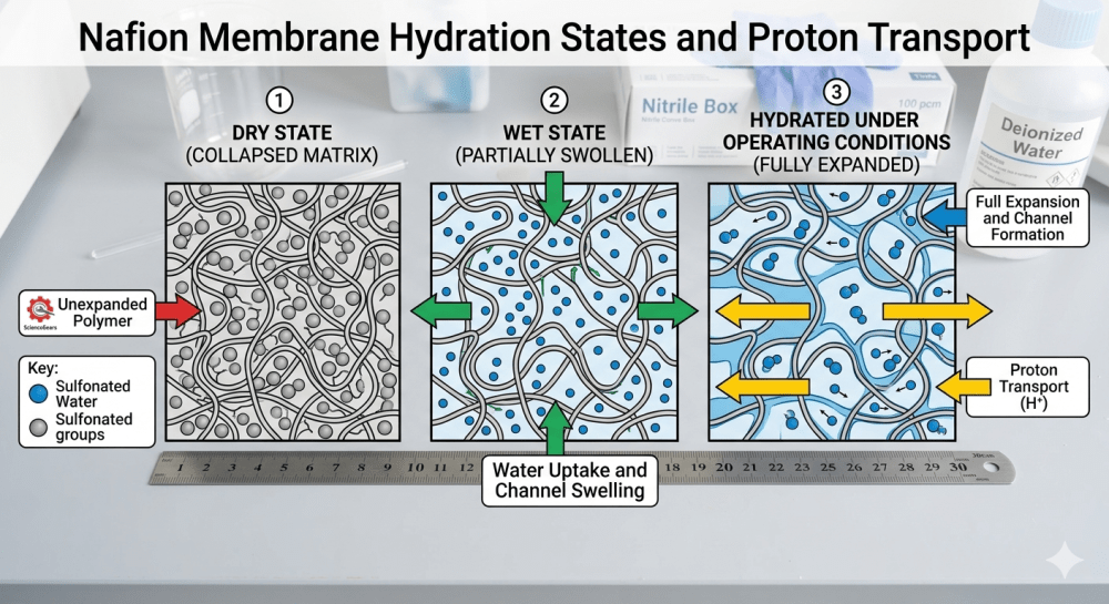
Caption: Nafion 117 (left, ~183 µm dry) vs Nafion 212 (right, ~51 µm dry). The thickness difference affects ohmic resistance, gas crossover, and mechanical handling during MEA assembly.
3.3 Nafion 117 — the Workhorse
Nafion 117 is a common choice for many lab-scale experiments because of its mechanical robustness and handling convenience. Its 183 µm dry thickness provides mechanical robustness during handling and assembly, low gas crossover under pressure, and sufficient ionic conductivity for most current densities encountered in research settings. It is particularly well suited to bench-top H-cell electrochemistry and MEA testing where mechanical robustness outweighs the need for minimum ohmic resistance.
3.4 Nafion 212 — the Thin-Film Choice
Nafion NR212 (51 µm dry) has a substantially lower area-specific resistance (ASR) than Nafion 117, which translates directly into lower cell voltage at a given current density. It is the preferred choice for MEA fabrication, high-performance PEMFC testing, and electrolysis applications where minimising ohmic losses is a priority. Handle with care — it is more prone to wrinkling during dry assembly than the thicker grades.
3.5 Nafion 115 — the Middle Ground
Nafion 115 sits between 117 and 212 in both thickness and ASR. It is a sensible choice when you require lower resistance than 117 but greater mechanical robustness than 212 — for instance, in early-stage MEA prototyping where the membrane will be assembled and disassembled repeatedly.
3.6 Nafion 211 — for Ultra-Thin Applications
At approximately 25 µm dry, Nafion NR211 is used in applications demanding very low membrane resistance, such as high-frequency EIS studies, thin-film CCM fabrication, or advanced MEA designs where the membrane contribution to total cell resistance must be minimised. It requires careful handling and is not recommended for bench-top H-cell use.
4 When to Choose an Anion Exchange Membrane (AEM)
The growing interest in green hydrogen and CO₂ electroreduction has significantly expanded the role of anion exchange membranes in research laboratories over the past decade. The key driver is the compatibility of AEMs with alkaline electrolytes, which in turn enables the use of earth-abundant transition metal catalysts rather than platinum-group metals.
4.1 Fumasep FAA-3 — the Research Standard
Fumasep FAA-3 grades, including commonly used 50 µm and 75 µm variants, are frequently referenced in academic work on alkaline electrochemical systems. Their fixed cationic groups support anion transport, but conductivity, stability, and suitability depend on the exact grade, counter-ion form, electrolyte, temperature, and operating time.
4.2 CO₂RR Applications — a Critical Nuance
Researchers working on CO₂ electroreduction should be aware that hydroxide ions in the cathode compartment react with dissolved CO₂ to form carbonate and bicarbonate. This carbonate crossover through the AEM is a genuine experimental complication: it reduces the local OH⁻ concentration, lowers carbonate conductivity compared to hydroxide, and can precipitate salts at the membrane interface. When using an H-cell configuration for CO₂RR, this effect must be accounted for in your Faradaic efficiency calculations. Some researchers elect to use Nafion under these conditions to eliminate anion crossover, accepting the trade-off of an acidic cathode environment.
4.3 Limitations of AEMs
Many AEMs are more sensitive than PFSA membranes to strongly alkaline, oxidising, or high-temperature conditions. They are generally not selected for acidic proton-conducting systems, and long-term operation should be checked against the specific membrane datasheet and operating environment.
5 Cation Exchange and Bipolar Membranes — Niche but Powerful
5.1 Cation Exchange Membranes for Electrodialysis
Fumasep FKS cation exchange membranes are designed for selective monovalent cation transport in electrodialysis and ion separation applications. Unlike Nafion, which is designed for proton conductivity in a PEM system, FKS membranes are engineered for selective Na⁺ or K⁺ transport from mixed-cation solutions relevant in desalination research, pharmaceutical purification, and ion-selective sensor development.
For researchers using electrochemical cells for ion separation studies, CEM selection is governed primarily by ionic selectivity coefficient, membrane resistance, and chemical stability in the specific electrolyte, rather than by proton conductivity or gas crossover.
5.2 Bipolar Membranes for pH-Gradient Applications
Bipolar membranes are an underutilised tool in the research laboratory. Their water dissociation capability allows you to maintain different pH values on each side of the membrane simultaneously — a feature that is difficult to achieve in the same way with a conventional CEM or AEM. This is valuable in CO₂ capture loop experiments, where you may want an alkaline environment for CO₂ absorption and an acidic environment for CO₂ release, within the same electrochemical device.
They are also increasingly used in paired electrosynthesis where an oxidation reaction at the anode and a reduction reaction at the cathode are deliberately run in different pH regimes to optimise selectivity for each half-reaction independently.
6 Application-by-Application Decision Guide
The table below is designed to be used directly at the point of experimental design. For each common electrochemical application, it identifies the recommended membrane, the key selection rationale, and relevant considerations.
| Application | Recommended Membrane | Why | Key Consideration |
|---|---|---|---|
| PEM fuel cell (PEMFC) | Nafion 117 or NR212 | High proton conductivity, chemical stability in H₂/O₂ | Use 212 for lower ohmic resistance; 117 for robustness |
| PEM water electrolysis (PEMWE) | Nafion 117 | Withstands high current density and elevated pressure | Design gasket to hydrated thickness (~230 µm) |
| AEM water electrolysis (AEMWE) | Fumasep FAA-3-50 | OH⁻ transport, stable in 1 M KOH | Not suitable for acidic media |
| CO₂ electroreduction H-cell | Nafion 117 or Fumasep FAA-3 | Depends on anolyte pH | Account for carbonate crossover with FAA-3 |
| Redox flow battery | Membrane depends on electrolyte chemistry and target ion selectivity | Balance ionic conductivity against active-species crossover | Confirm membrane choice against the specific redox couple and datasheet |
| Electrodialysis/ion separation | Fumasep FKS | Monovalent cation selectivity | Match membrane to target ion |
| MEA fabrication and testing | Nafion NR211 or NR212 | Thin film, low ASR, good CCM adhesion | Handle carefully; avoid wrinkling during hotpress |
| pH-gradient electrosynthesis | Bipolar membrane | Simultaneous acid/base generation at interface | Requires reverse-bias operation |
| Alkaline electrosynthesis | Fumasep FAA-3 | OH⁻ medium compatible | Monitor carbonate precipitation at high current |
| H-cell membrane characterisation | Nafion 117 | Robust, reproducible, well-characterised baseline | Pre-treat before use (see Section 7) |
7 Practical Considerations Before You Order
Selecting the right membrane type and grade is necessary but not sufficient. The following practical factors are frequently overlooked and can have a meaningful impact on experimental reproducibility.
7.1 Pre-Treatment Protocol
Nafion pre-treatment depends on the membrane form, supplier condition, and application. A commonly used academic pre-treatment sequence involves peroxide, deionised water, dilute acid, and final rinsing, but researchers should confirm the appropriate procedure from the current datasheet, supplier guidance, or laboratory protocol before use. This procedure ensures consistent ionic conductivity and removes surface contaminants that could interfere with catalytic measurements. Skipping pre-treatment is a common source of irreproducibility, particularly when comparing results between laboratories.
7.2 Hydration and Storage
Once Nafion membranes have been pre-treated and hydrated, avoid repeated drying and rehydration because this can affect membrane dimensions and ion-transport behaviour. Fumasep AEM and CEM membranes have their own storage conditions specified in their respective datasheets — always consult these before first use.
7.3 Cutting to Size and Cell Compatibility
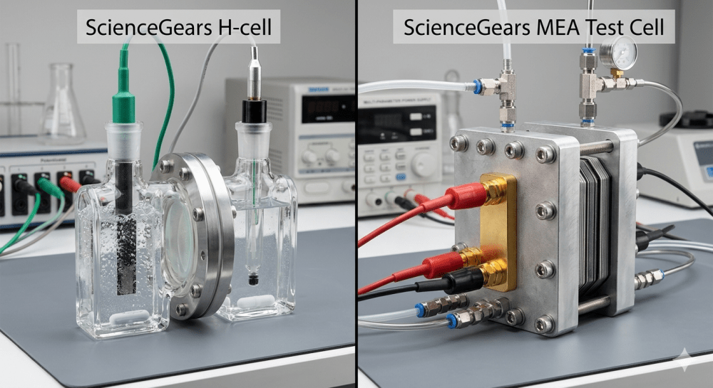
Most membranes are supplied in sheet form and require cutting to the active area of your specific cell. When using ScienceGears MEA test cells, cut the membrane to suit the selected active area and gasket geometry, allowing sufficient overlap into the sealing region to minimise electrolyte bypass. Use a sharp scalpel or die-cutter; scissors introduce edge defects that nucleate mechanical failure under compression.
7.4 Gasket Design and Compression
Gasket thickness must be matched to the wet or hydrated membrane thickness, not the dry value quoted in the datasheet. Over-compression reduces membrane conductivity by collapsing the hydrated polymer network; under-compression allows electrolyte bypass and increases contact resistance at the electrode interface. For MEA test cell configurations, gasket thickness should be selected based on the membrane, electrode stack, compression target, and sealing design rather than using a universal percentage rule.
7.5 Compatibility with Your Potentiostat and Cell Format
Many of the membranes described in this guide can be paired with ScienceGears electrochemical cells, H-cells, and MEA test cells, provided the membrane dimensions, chemistry, temperature range, and sealing requirements are suitable for the application. If you are working with a commercial potentiostat — Zahner, Squidstat, CorrTest, or similar — and require guidance on cell configuration for EIS or chronoamperometry measurements, our technical team can advise on the correct setup for your specific instrument and membrane combination.
8 How ScienceGears Supports Your Membrane Research
ScienceGears is founded and led by PhD-trained electrochemists and researchers who have worked in similar laboratory environments, run comparable experiments, and faced the same practical decisions described in this guide. That experience shapes how we support researchers across Australia and New Zealand.
Our ion-exchange membrane range includes Nafion 115, 117, 211, and 212, Fumasep FAA-3 (AEM), Fumasep FKS (CEM), and bipolar membranes, with selected products available for local AU/NZ supply depending on current stock. These membranes are compatible with our full range of electrochemical cells, H-cells, MEA test cells, PEMWE test stations, and AEMWE test stations.
Beyond supply, we offer:
- Technical consultation on membrane selection for your specific application, cell format, and operating conditions
- Custom cutting and sizing assistance for non-standard active areas
- Integration guidance for pairing membranes with ScienceGears MEA complete packages and potentiostat setups
- Application notes and resources available through our publications and resources library
If your application is not covered by the decision matrix in Section 6, or if you are working with a novel electrolyte system or non-standard cell geometry, our technical team is available to discuss bespoke recommendations.
9 Frequently Asked Questions
These are the questions we receive most often from researchers and lab managers working on membrane selection and electrochemical cell setup.
Q1 Can I reuse a Nafion membrane after an experiment, and how do I know when to replace it?
Nafion membranes can sometimes be reused across multiple experimental runs, but only with important caveats. After each experiment, rinse the membrane thoroughly with deionised water to remove electrolyte residue, then store it submerged in deionised water at 4–8 °C in a sealed container. Do not allow it to dry out between runs once it has been pre-treated and hydrated, as repeated drying causes irreversible structural changes to the ionic channels.
Signs that a membrane should be replaced rather than reused:
- Discolouration — yellowing or browning indicates oxidative degradation of the polymer backbone or contamination from catalyst or electrolyte species
- Visible pinholes or tears — even a small defect causes electrolyte crossover that invalidates Faradaic efficiency measurements
- Blistering or delamination — common after autoclaving (avoid autoclaving Nafion; use chemical pre-treatment instead) or after exposure to incompatible solvents
- Measurable performance decline — if EIS shows a significant increase in membrane resistance compared to the membrane’s baseline, it is time to replace
Nafion service life in electrolyser applications varies widely depending on membrane grade, cell design, catalyst, water quality, temperature, pressure, current density, and operating protocol. For intermittent lab use in H-cells or MEA test cells, a well-maintained membrane can last many months. However, for publication-quality data, using a fresh, pre-treated membrane for each new experimental series is strongly recommended to eliminate membrane history as a variable.
Q2 Does Nafion membrane expire or degrade during storage — and how should I store unused membranes?
This is one of the most frequently asked questions on researcher forums, arising when researchers find old membrane sheets in lab storage and are unsure whether they are still viable.
Nafion membranes do not have a strict expiry date, but their properties do degrade over time depending on storage conditions:
- Dry storage (as-received, sealed): Membranes stored in their original sealed packaging, away from UV light, heat, and contamination, may remain usable for extended periods, but performance should be verified before quantitative experiments. The as-received form (sodium or acid form, dry) is the most stable for long-term storage.
- Dried membranes that were previously hydrated: These are problematic. Once a membrane has been pre-treated and hydrated, drying it causes irreversible structural changes to the ionic channels. Do not dry a pre-treated membrane.
- Aged membranes showing physical changes: If you have an old membrane sheet that has been stored loosely, the recommended approach is to treat it with double-distilled water followed by 5 wt% hydrogen peroxide and again with double-distilled water before use — this removes accumulated impurities and partially restores surface properties.
For unused membranes, follow the supplier’s storage instructions and keep the original package sealed until use. For pre-treated hydrated Nafion membranes, avoid drying; store wet in clean deionised water unless your lab protocol or supplier datasheet specifies otherwise.
If in doubt about a membrane’s condition, measure its proton conductivity via EIS before using it for data collection. A reading significantly below the expected value for the membrane grade, hydration state, and test conditions may indicate incomplete hydration, contamination, or degradation.
Q3 Why is my Nafion membrane turning yellow and does it affect performance?
Yellowing of a Nafion membrane during or after an experiment is a commonly observed phenomenon. There are three main causes, each with different implications:
Cause 1: Iron or transition metal contamination A common cause in research settings. If your electrolyte, catalyst ink, or cell hardware contains iron, nickel, cobalt, or other transition metal ions, these can exchange into the Nafion membrane’s sulphonate sites, replacing protons and causing visible discolouration ranging from pale yellow to orange-brown. This significantly reduces proton conductivity and the membrane should be replaced. It also indicates a cell contamination issue that needs to be addressed at the hardware level.
Cause 2: Oxidative degradation Prolonged exposure to highly oxidising conditions particularly at the anode in water electrolysis generates radical species (hydroxyl, peroxyl) that attack the ether side chains of the PFSA backbone. Excessive membrane swelling under fully humidified conditions and decreased mechanical integrity at higher temperatures contribute to delamination, cracking, and shortened operational lifespan. Yellowing in this context is accompanied by increased fluoride release into the electrolyte and measurable thinning of the membrane over time.
Cause 3: Catalyst or ink contamination If Nafion has been in contact with carbon-based catalyst inks, the membrane can absorb organic species and appear darker or yellowish. This is often reversible with the standard peroxide pre-treatment (boiling in 3% H₂O₂ for 60 minutes), provided the contamination is recent.
What to do: If yellowing is localised, try re-treating the membrane through the standard pre-treatment protocol (Section 7.1 of this guide) before discarding. If discolouration is uniform and accompanied by visible blistering, brittleness, or a significant drop in measured conductivity, replace the membrane.
Q4 Can I use the same membrane for both fuel cell and electrolyser experiments, or do I need separate membranes?
Technically, Nafion 117 is chemically compatible with both PEMFC and PEMWE operating environments, and the same membrane grade is commonly used in both applications in research settings. However, using the same physical piece of membrane for both experiments is not recommended, for several reasons:
Operating history matters: A membrane that has been used in a fuel cell (where it has been exposed to humidified H₂ and O₂, possible platinum catalyst contamination, and moderate temperature cycling) carries that history into a subsequent electrolyser experiment. Catalyst crossover from the MEA layers, electrolyte residue, and accumulated chemical degradation will affect performance data in ways that are difficult to account for.
Different cell geometries: PEMFC and PEMWE cells typically use different active areas, gasket designs, and compression specifications. A membrane cut and compressed for one cell format is not straightforwardly transferable to another without re-evaluating the gasket geometry against the membrane’s current hydrated thickness (which changes with history).
What is appropriate: Using the same grade of Nafion (e.g. Nafion 117) as a common material across both experimental systems sourced from the same batch for consistency is good practice and facilitates cross-comparison of results. But use a fresh, pre-treated piece of membrane for each experimental campaign. Given the relatively low per-sheet cost of Nafion compared to the time cost of irreproducible results, this is a straightforward call. Order Nafion in sheet form from ScienceGears →
Q5 How do I know if my membrane is properly hydrated before running an experiment?
Inadequate membrane hydration before an experiment is a silent source of irreproducibility: the membrane can appear assembled correctly, but its ionic conductivity may be substantially below the fully hydrated value, leading to anomalously high cell voltages, poor current density, and EIS spectra that suggest high ohmic resistance without any obvious hardware fault.
A properly hydrated Nafion membrane can be verified by three methods, in increasing order of rigour:
Method 1 Visual and tactile check (qualitative) A fully hydrated Nafion 117 membrane is visibly more translucent than the dry membrane and has a slight flexibility and suppleness when handled with tweezers. A dry or partially hydrated membrane feels stiffer and more opaque. This is a useful quick check but not reliable enough for publication-quality work.
Method 2 Weight measurement (semi-quantitative) Weigh the dry membrane (as received), then weigh it again after completing the full pre-treatment and hydration protocol. Nafion 117 can absorb a substantial fraction of its dry weight in water, depending on pre-treatment, temperature, and measurement method (water uptake = (W_wet − W_dry) / W_dry × 100%). A reading in this range confirms adequate hydration. Values below 15% suggest incomplete hydration; values above 40% may indicate membrane swelling from elevated temperature treatment.
Method 3 EIS measurement (quantitative) The most rigorous verification. Measure the membrane resistance directly using electrochemical impedance spectroscopy in your assembled cell at open circuit. A fully hydrated Nafion 117 at 25 °C may show an ASR in this approximate range under suitable test conditions, but the measured value depends on cell geometry, contact resistance, hydration, electrolyte, and measurement method. A reading significantly above this range indicates incomplete hydration or membrane degradation. This method has the added benefit of giving you a baseline membrane resistance value to reference throughout your experimental series.
Q6 Is Nafion safe to handle in the lab, and are any specific precautions required?
Nafion membranes in their solid, hydrated sheet form can be handled using standard laboratory precautions; nitrile gloves are recommended primarily to prevent oil and protein contamination from skin contact, which can affect membrane conductivity. The membrane itself is chemically inert under normal handling conditions.
The precautions that do matter are:
- Do not heat Nafion membranes outside the conditions recommended by the manufacturer or your validated MEA hot-pressing protocol. Heating fluoropolymers above their safe operating range can produce hazardous decomposition products, so elevated-temperature processing should be performed with appropriate ventilation and safety controls. This is only relevant for hotpressing MEAs (typically done at 120–140 °C for 3 minutes) or accidental contact with hotplates.
- Avoid DMSO and DMF at elevated temperatures, as these solvents can swell or damage Nafion, which is relevant if you are working with organic electrolyte systems.
- Nafion dispersions require more care than the membrane because the carrier solvent can be flammable; handle dispersions in a well-ventilated area away from ignition sources.
- Pre-treatment chemicals — including peroxide and dilute acid steps where used — require standard chemical handling precautions (lab coat, gloves, eye protection, fume hood for heated acid work).
Spent Nafion membranes are typically handled according to standard institutional laboratory waste protocols; however, confirm with your institution’s safety officer if the membrane has been contaminated with hazardous catalyst materials such as platinum-group metals, transition metals, organic solvents, or toxic electrolytes.
Further reading and related resources
On the ScienceGears blog: What is MEA? Membrane electrode assembly complete guide and H-cell electrochemical reactors: dual-chamber systems guide
Cluster articles in this content series — go deeper on any topic:
- Nafion 117 vs 212 vs 115: which grade is right for your experiment?
- Nafion vs Fumasep AEM: PEM vs AEM for water electrolysis
- Cation vs anion vs bipolar membranes: complete ion-exchange guide
- Membrane selection by application: fuel cell, electrolyser, H-cell, and MEA test cell
Get in touch
Not sure which membrane or cell format is right for your experiment? Contact our technical team — we aim to respond within one business day and are happy to discuss your specific research setup before you commit to an order.