
By the end of this guide you will be able to choose a cathode and anode pairing for a sodium-ion half-cell or full-cell study, plan sodium-ion coin-cell studies using a compatible electrode pair, collector, electrolyte and separator, and assess the first-cycle voltage profile while distinguishing material behaviour from possible assembly artefacts. Use institutionally approved procedures for sodium-metal handling and cell assembly.
1. Why sodium-ion work is not lithium-ion work with a different salt
Most researchers arrive at sodium-ion chemistry carrying a lithium-ion protocol. The instinct is to swap the lithium salt for a sodium salt, change the active powders, and run the same formation routine. The first cycle then looks wrong: the anode loses far more charge than a graphite cell would, the cathode powder has gone off-colour on the shelf, and the capacity you calculated from the literature does not appear. These symptoms do not automatically mean the cell is faulty: they call for checks of sodium-ion chemistry, powder handling, cell balance and assembly conditions.
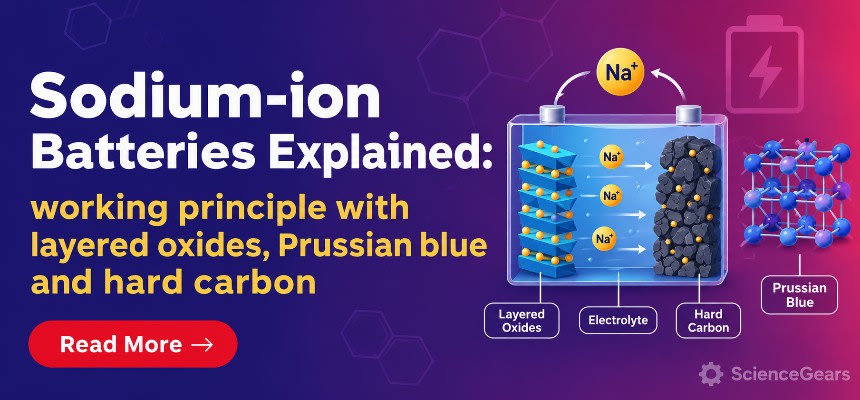
The overall principle is familiar. Sodium ions shuttle between two host materials through a liquid electrolyte, and electrons travel through the external circuit. What changes is the detail. In many practical non-aqueous sodium-ion designs, the anode is hard carbon rather than graphite: ordinary carbonate-electrolyte systems do not enable high-capacity sodium intercalation into graphite, although specialised co-intercalation systems are exceptions. The cathode families are different: layered oxides, Prussian blue analogues and polyanionic phosphates, each with its own handling problem. Aluminium can serve as the current collector on both coated electrodes in many sodium-ion full cells because it does not form an appreciable Na–Al alloy under typical hard-carbon operating conditions. Hard-carbon first-cycle losses are often substantial, although cathode-side irreversible losses can also matter; the usable sodium inventory must therefore be considered explicitly in full-cell design.
This guide covers the three material families most researchers meet first: hard carbon for the anode, and layered oxides and Prussian blue analogues for the cathode. It then follows the practical chain through to a working coin cell: pairing logic, electrode formulation, electrolyte and separator choice, assembly, formation and interpretation. Each section ends with a decision you can make at the bench.
A note on scope. Polyanionic cathodes such as sodium vanadium phosphate are mentioned only briefly, and sodium–sulfur, sodium–oxygen and solid-state sodium systems are outside this guide. A short note in section 5 lists what has been left out and why.
For a quick map of the powders referred to throughout, the sodium-ion battery materials category groups the hard carbons, layered oxides and Prussian analogues in one place, and the wider battery materials range covers the binders, carbons, foils and electrolytes needed around them.
2. How a sodium-ion cell works: the rocking-chair principle
If you cannot sketch where the sodium is at each stage of a charge cycle, you will struggle to interpret a voltage curve. The sodium-ion cell is a rocking-chair system, the same idea as lithium-ion: the ions rock between a cathode host and an anode host, and metallic sodium deposition is not part of the intended reversible storage mechanism in a conventional hard-carbon full cell.
On charge, the cathode is oxidised. Sodium ions leave the cathode lattice, cross the separator in the electrolyte, and enter the anode, while electrons are driven through the external circuit to the anode. On discharge the process reverses and the cell delivers work. In shorthand, with a layered oxide cathode, the charge reaction at the cathode is NaₓTMO₂ → Na(x−y)TMO₂ + y Na⁺ + y e⁻, and at the hard carbon anode it is C + y Na⁺ + y e⁻ → Na_yC, where TM denotes the transition-metal constituent(s); these are simplified host reactions that omit interphase formation and other side reactions. The cell voltage is the difference between the two electrode potentials, so a higher-potential cathode or a lower-potential anode raises it.
The sodium ion is larger than the lithium ion, and that has three practical consequences. It pushes the anode towards disordered carbons with wide interlayer spacing and nanopores, it makes the cathode lattices undergo different phase changes on desodiation, and it can change ion-transport and phase-transition behaviour in specific host structures. In one study of commercial cylindrical sodium-ion cells, the hard-carbon electrode showed slower apparent charge-storage kinetics than the layered-oxide cathode. If full-cell rate capability is disappointing, examine both electrodes and their interphases rather than assuming the anode is always responsible.
Another point for lithium-ion converts: although some sodium cells use carbonate-based electrolytes similar to lithium-ion systems, the surface films that form on the electrodes matter just as much. The solid electrolyte interphase on hard carbon consumes sodium on the first cycle, and that sodium is lost to the cell. Much of the rest of this guide is about managing that loss.
Bench decision. Before you choose any material, decide whether your study is about the cathode, the anode or the full cell. Na-metal counter-electrode half-cells are commonly used to characterise individual electrodes, but their results can contain counter-electrode artefacts; a balanced full cell is needed to evaluate the selected cathode and anode together. Plan the cell type first, then pick powders. The cathode materials and anode materials categories are organised on that logic, and the electrochemical cell selection guide helps when you need a three-electrode format to separate the two electrode contributions.
3. Hard carbon: reading the slope, the plateau and the first-cycle loss
You assemble a hard carbon half-cell, run the first sodiation, and the profile bears no resemblance to the sharp, flat graphite staging curves you know from lithium-ion work. A long sloping region leads into a low-voltage plateau, and when you reverse the current a substantial fraction of the capacity does not come back. Such behaviour is frequently observed in hard carbon, but its interpretation depends on the carbon structure, electrolyte and test protocol.
Hard carbon is a non-graphitising carbon: small, curved, misoriented graphene-like domains with defects, wide interlayer spacing and nanopores, some of them closed. Published reviews describe sodium storage as a combination of three processes: adsorption at defects and surfaces, insertion between carbon layers, and filling of nanopores. The sloping region is often associated with defect- and surface-related storage, while interlayer insertion and pore filling can contribute to the low-voltage plateau; these assignments are not universally unique. Reviews do not agree on the exact voltage boundaries. One places the slope between 1.0 and 0.2 V, another between 2.0 and 0.1 V versus Na⁺/Na, and the plateau below roughly 0.1 V in some accounts and between 0.2 and 0.05 V in others. Diffraction, spectroscopic and modelling studies indicate that insertion and pore filling can coexist, with their contributions depending on pore structure, interlayer spacing and defect chemistry. Treat the mechanism as settled in outline and still contested in detail, and do not assign voltage windows to mechanisms in your own paper without citing the specific carbon you measured.
First-cycle irreversible capacity can arise from electrolyte reduction and solid-electrolyte-interphase (SEI) formation, sodium trapping and other parasitic reactions. Their relative contributions depend on surface chemistry, carbon structure and electrolyte formulation. A high-surface-area, defect-rich carbon will lose more on the first cycle even if its reversible capacity looks attractive. Spherical or lower-surface-area grades may improve packing and first-cycle efficiency, but the outcome, including rate behaviour, must be established experimentally at matched loading and formulation. A 2025 modelling study of commercial-scale cells named the hard carbon as the bottleneck towards higher energy density, which tells you where the field's effort is going.
At the bench, plot dQ/dV alongside the voltage profile for your first three cycles. It shows whether the slope and plateau contributions are stable or drifting, and it may reveal changes in the voltage response, but peak changes alone do not uniquely identify an interfacial mechanism. Report the first-cycle efficiency as an average across at least three cells, because it is the figure most sensitive to electrode preparation.
ScienceGears supplies two hard carbons for this work. Na-HC01 irregular hard carbon is a non-graphitised powder of irregular flake morphology, and its product page reports a reversible capacity of approximately 250 mAh g⁻¹ under supplier-described conditions; this is not a guaranteed value for every lot or test setup. The product description discusses use with common non-aqueous sodium electrolytes and organic or water-based binder systems; verify the exact electrolyte and electrode-processing conditions for the intended study. Na-HC02 high sphericity hard carbon is the spherical grade, and the category overview positions it for improved packing and coating uniformity when you move towards higher loadings. A reasonable plan is to screen with the irregular grade and move to the spherical grade when you start increasing areal loading.
Bench decision. If your goal is a mechanism or an electrolyte study, use one hard carbon and change only the electrolyte. If your goal is electrode engineering, compare the two morphologies in the same electrolyte at matched loading, and report first-cycle efficiency with both.
4. Layered oxides: O3, P2 and the air-sensitivity problem
A layered oxide cathode powder that performed well when freshly synthesised can deliver much poorer capacity after a week on an open shelf. For air-sensitive compositions, exposure to moisture and carbon dioxide can modify the surface and generate alkaline degradation products; mechanical and electrochemical factors may also contribute. Many sodium-ion cathode disappointments start there, not in the cell.
Layered sodium transition-metal oxides, written NaₓTMO₂, consist of transition-metal oxide slabs with sodium between them. The notation O3 and P2 describes the sodium coordination (octahedral or prismatic) and the number of distinct transition-metal-oxide layer stacking positions in the repeat unit. Many O3 compositions are initially more sodium-rich, but their phase evolution and rate behaviour are composition-dependent. Many P2 compositions begin with lower sodium content and can offer favourable transport; high-voltage transitions may involve O2, OP4 or other phases depending on composition and cut-off. No universal 4.2 V threshold applies. Peer-reviewed reviews also report that most O3 materials are air and moisture sensitive. For particular Na–Fe–Mn oxides, published O3 and P2 variants have shown different measured capacities, but a general capacity ranking is not transferable to every composition, cycle window or synthesis route.
Air exposure matters because the surface reaction forms sodium carbonate and bicarbonate, which can create alkaline surfaces in water-containing environments and impede charge transfer at the electrode–electrolyte interface. In practice that shows up as high first-cycle polarisation and irreproducible results between batches.
ScienceGears offers three oxide cathodes that sit in this territory, although they are not all strictly layered:
- NFMS is NaNi₀.₃₃Fe₀.₃₃Mn₀.₃₃O₂, a multi-metal composition reported in O3-type forms in the literature; verify the actual supplied phase by X-ray diffraction (XRD). The category overview positions it for balancing capacity and stability and for comparative ageing studies.
- NFM is Na₂/₃Fe₁/₂Mn₁/₂O₂, a composition reported as P2-type in the literature, and is aimed at cost-leaning Fe/Mn cathode research.
- NMO is catalogued as NaNi₀.₅Mn₁.₅O₄. Its structural classification cannot be established from the empirical formula alone: spinel-derived sodium-exchange materials have been reported, whereas the current catalogue description calls this product layered. Do not assign either phase or published capacity figures to the supplied powder without a lot-specific XRD pattern, phase identification and electrochemical test conditions. Treat it as a separately verified NMO candidate rather than a confirmed member of the O3/P2 families.
Treat moisture-sensitive oxide lots conservatively, while recognising that air stability varies with exact composition, phase and surface history. Weigh and mix inside a glovebox or dry room if you can. If you cannot, minimise exposure time, record it in your methods, and compare against a sealed reference lot. Use the material-specific storage and drying recommendations; do not assume that heating or aqueous exposure is harmless, and select a solvent system validated for the actual powder. Alkaline surface species can also react with binder solutions, so a slurry that thickens unexpectedly is a warning that surface chemistry has changed.
Bench decision. Consider a characterised P2-type composition when sodium inventory and possible high-voltage transitions can be managed (section 6); consider a characterised O3-type composition when its initial sodium content and phase behaviour suit the intended full cell. Neither structure guarantees higher capacity or faster kinetics. Whichever you choose, choose an electrode-specific voltage window supported by literature and characterisation, then check possible phase changes using suitable methods such as XRD and differential-capacity analysis. The cathode materials category lists the full range.
5. Prussian blue and Prussian white: open frameworks, vacancies and water
Two batches of a Prussian blue cathode from the same supplier can give capacities that differ by tens of mAh/g, and the coulombic efficiency in the first cycles can be unusually low. Vacancy concentration, oxidation state, sodium content and different forms of water can contribute to this variability; some compositions also undergo genuine structural or chemical degradation.
Prussian blue analogues are open frameworks of transition-metal ions bridged by cyanide ligands, with large interstitial sites that host sodium ions. A useful general formula is NaₓM[Fe(CN)₆]₁₋ᵧ□ᵧ·nH₂O, where □ denotes a missing [Fe(CN)₆] unit and y is the vacancy fraction. Water can be interstitial or coordinated to metal sites near vacancies; vacancy and water content are important, but not the only, determinants of performance. Rapid precipitation creates many vacancies and traps interstitial water, which lowers capacity and cycling stability. A controlled synthesis of rhombohedral Prussian white with composition close to Na₁.₈₈Fe[Fe(CN)₆]·0.18H₂O reported an initial capacity of 158 mAh/g and 90% retention after 50 cycles, and identified increased polarisation on the 3 V plateau as coincident with a phase transition. The ideal sodium-rich Na₂Fe[Fe(CN)₆] composition has a theoretical capacity close to 170 mAh g⁻¹ for a two-electron reaction, before accounting for water, vacancies or inactive components; actual full-cell sodium supply depends on the analysed batch.
The terms Prussian blue and Prussian white are often used loosely. Prussian white is the more reduced, sodium-rich form, and Prussian blue is the more oxidised, sodium-poorer form. Because product naming is not a compositional certificate, establish the actual sodium content, iron oxidation state, vacancy fraction and water content of each lot before using its nominal identity for full-cell balancing.
ScienceGears lists PBAs Prussian blue powder, whose catalogue page gives Na₂FeFe(CN)₆ and a first-discharge capacity of at least 120 mAh g⁻¹ at 0.1 C between 2 and 4.0 V versus sodium under the supplier-listed test conditions. The page also describes casting on aluminium current collectors; performance remains lot- and protocol-dependent. PW Prussian white powder is also listed with the nominal formula Na₂Fe[Fe(CN)₆]. Because both catalogue entries show the same nominal stoichiometry, the listings do not by themselves establish a difference in sodium inventory or oxidation state. Confirm composition and phase with a batch-specific certificate or suitable analysis before treating the named powders as electrochemically distinct. Both grades may contain water and be humidity-sensitive.
When appropriate, assess moisture by a validated method such as thermogravimetric analysis (TGA), ideally complemented by structural or chemical characterisation. A TGA mass-loss curve alone does not establish a safe drying temperature: heating cyanide-coordinated materials can change the framework and, under decomposition conditions, release toxic products. Apply only a manufacturer-validated drying process under an institutional chemical-safety procedure, then record temperature, duration, atmosphere and transfer conditions. Do not assume that a dried powder retains its original phase or performance.

Bench decision. Consider a well-characterised Prussian blue analogue for rate-oriented studies, checking measured sodium inventory, vacancies and water; consider a layered oxide when its verified voltage profile, phase stability and air-handling requirements fit the study. Neither family guarantees the highest voltage or capacity.
6. Pairing cathode and anode: the sodium budget in a full cell
A cathode that looks excellent against sodium metal and an anode that looks excellent against sodium metal can still make a poor full cell. The reason is simple accounting. In a sodium-metal half-cell, the counter electrode usually provides a large excess of sodium. In an initially sodium-ion full cell without presodiation or other sodium-compensation additives, the initial cyclable sodium inventory comes principally from the cathode, and irreversible reactions can consume part of it.
Think of the cell as a budget. The cathode starts with a certain sodium inventory. On the first charge the hard carbon takes up sodium, and a fraction of that never returns because it forms the interphase or becomes trapped. The sodium left over defines the reversible capacity of the full cell. A sufficiently sodiated cathode can help accommodate that loss, but capacity retention also depends on accessible cathode capacity, irreversible cathode reactions, electrode balancing and the chosen voltage window. P2 compositions such as Na₂/₃Fe₁/₂Mn₁/₂O₂ begin with about two-thirds of a sodium per formula unit, so there is less inventory to absorb the anode's first-cycle loss. Sodium-rich Prussian white starts from a higher sodium content, which is one reason published work describes it as favourable for full cells.
Two design variables follow. The first is the capacity ratio between the electrodes. For hard carbon, which has the low-voltage plateau close to the sodium plating potential, a suitable negative-to-positive (N/P) reversible areal-capacity ratio can reduce the risk of sodium plating at high state of charge, but it does not by itself prevent plating under fast charge, low temperature or poor kinetic conditions. The second is the cell balance after formation: measure first-cycle uptake and release for both electrodes, then balance their reversible areal capacities and initial accessible sodium inventory using a defined formation window. Do not size a full cell from nominal powder capacity alone.
Published pairings give a useful sanity check. Individual reported Prussian blue analogue–hard carbon full cells show widely varying retention according to electrode balance, electrolyte and cycling conditions. A selected literature result should not be treated as a typical lifetime or compared directly with half-cell cycling. Energy-density figures also differ by what you count: gravimetric figures based on active material alone overstate cell-level performance, while gravimetric and volumetric energy density use different denominators and cannot be directly ranked without a common basis (see section 11).
For a first screening full cell, a sensible approach is one hard carbon with one cathode, balanced from measured half-cell data, with a second cathode family run in parallel for comparison. A characterised P2-type Fe/Mn NFM can be studied with Na-HC01 to evaluate its sodium inventory; for contrast, assess the catalogue-labelled PW Prussian white grade only after verifying its sodium content, iron redox state and water content (the PB/PW listings show the same nominal formula). Match reversible areal capacities and examine formation efficiency alongside measured cathode/anode balances; efficiency alone does not isolate sodium inventory.
Bench decision. Run half-cells first, calculate the anode first-cycle loss, then build full cells from those measurements. Report the capacity ratio you used, because without it nobody can reproduce your full-cell data. The anode materials and cathode materials categories are the starting points for sourcing both halves of the pair.
7. Electrodes, binders and current collectors
An electrode that delaminates, cracks on drying, or shows a high and drifting impedance is often blamed on the active material. In sodium-ion work the formulation and the foil are just as often responsible, and some sodium-ion design options differ from conventional lithium-ion practice.
The first is the current collector. Lithium-ion anodes use copper because lithium alloys with aluminium at low potentials. Sodium does not alloy with aluminium at typical anode potentials, so aluminium foil can serve on both electrodes. Reviews and industry analyses point to a cost benefit and a weight benefit: one techno-economic scenario estimated approximately 9% lower cell-material cost and 3% lower overall battery cost from replacing an anode copper foil, but these are model-dependent estimates rather than universal savings. In a coin cell the saving is trivial, but the practical benefit is real: one foil type, one cleaning routine and one stock item. Two cautions apply. Direct Na-metal deposition on aluminium is a separate, electrolyte- and surface-dependent research problem; unmodified aluminium is not a universally suitable plating substrate. And aluminium foil carries a native oxide layer, so surface condition affects contact resistance; use the same foil lot across a comparison. ScienceGears lists current collector foils among its battery materials; confirm the foil type and thickness for your cell format when you order.
The second consideration is the binder and solvent system. Hard carbon is compatible with both PVDF in NMP and water-based binders such as CMC with SBR, and the water-based route is attractive for its lower cost and easier handling. Many layered oxides are moisture-sensitive, so dry organic coating is a conservative starting point; validated aqueous processing is possible for some compositions and must be justified with material-specific stability data. Prussian analogues can be cast on aluminium collectors, but water content must be controlled whichever solvent you use. The binders, solvents and additives category covers both families.
Conductive carbon is the third variable. A fine graphite additive builds an electron-percolation network between active particles and the foil, which lowers internal resistance and helps rate behaviour. KS-6 conductive graphite powder is listed at 1 to 5 µm for use in lithium-ion and sodium-ion workflows, with either PVDF/NMP or CMC/SBR systems. The wider conductive carbons range gives alternatives if you need a different surface area or structure. Hard carbon may require a different conductive-additive fraction from oxides or Prussian analogues, depending on electrode conductivity and loading, and you should keep the additive content constant when you compare two actives.
Three habits make electrode data comparable. Record areal loading in mg/cm² for every electrode and keep it within a narrow band across a comparison. Dry the coated electrode thoroughly under vacuum before assembly. And use the same calendering step on every electrode, because porosity changes both rate behaviour and first-cycle loss.
Bench decision. Choose the binder system by the cathode, not by habit: dry organic for layered oxides, water-based or organic for hard carbon. For conventional coated-electrode sodium-ion full cells, aluminium foil is a common choice on both sides; in sodium-metal half-cells the sodium counter electrode is not an aluminium-coated composite electrode.
8. Electrolytes and separators
Two cells with the same electrodes can give noticeably different first-cycle efficiencies because of the electrolyte alone, and it is easy to attribute that to the material. In sodium-ion cells the electrolyte largely determines the interphase on hard carbon, and the interphase determines how much sodium is lost.
A 2025 review of hard carbon anodes links electrolyte formulation directly to the composition and stability of the solid electrolyte interphase, and identifies that interphase as a critical factor for high initial coulombic efficiency and long-term cycling. Practical sodium-ion electrolytes use a sodium salt in organic solvents. NaPF₆ and NaClO₄ are used in published non-aqueous sodium-ion studies, but salt–solvent–electrode compatibility must be checked for the exact system. Carbonate solvent blends are the common starting point in the published literature. NaClO₄ is an oxidiser and needs careful handling, and NaPF₆ is moisture sensitive and can generate hydrofluoric acid on contact with water, so both require dry storage and your institution's safety procedures. Water content in the electrolyte is not a detail: it affects the interphase, the Prussian analogue chemistry and the layered oxide surface.
The fair-comparison rule is to change one variable at a time. If you compare two salts, keep the solvent blend, additive content, separator, electrode loading and rest time constant. If you test an additive, test it in the baseline electrolyte rather than in a new formulation. Without a controlled baseline, apparent changes in first-cycle efficiency cannot be attributed reliably to the tested variable.
The separator is easier to overlook. Polyolefin membranes and glass-fibre separators are both used in published coin-cell work, and they wet differently, hold different volumes of electrolyte and add different impedance. Glass-fibre separators generally retain more electrolyte, while thinner polyolefin membranes may reduce separator volume; wetting, puncture resistance and compatibility depend on the specific material and assembly. Choose one and keep it constant across a comparison. Volume of electrolyte per cell also matters in a coin cell, so dispense it with a pipette and record the volume in µL.
Electrolytes and salts at ScienceGears covers liquid formulations and sodium salts, and the category notes that the right electrolyte strategy depends on the cathode and anode chemistry, voltage window and temperature range. Separators and membranes covers the separator options.
Bench decision. Fix an electrolyte, a separator and an electrolyte volume as your baseline before you start screening materials. Change them only in a dedicated study with a single variable.
9. Coin-cell assembly, formation and reading the first cycle
Replicate coin cells may show scatter from both material variability and assembly effects, including stack alignment, electrolyte volume, crimp pressure, moisture and spacer thickness. A sodium-ion coin cell is also less forgiving than a lithium-ion one because of how reactive the sodium metal counter electrode is in a half-cell.
A common illustrated CR2032 sodium-metal half-cell stack, from one case towards the other, includes the coated working electrode on its current collector, separator with electrolyte, sodium-metal counter electrode, spacer, spring and the opposite case; actual orientation and spacer order depend on the chosen hardware and validated cell design. Electrolyte is added to the electrode and separator before closing. Do not adopt published spacer or spring dimensions without checking the particular case, gasket, separator and sodium thickness: sodium metal is soft and compression affects contact and short-circuit risk.

Sodium-metal half-cells require trained operators, a suitably controlled dry inert atmosphere and an institution-approved alkali-metal handling, fire and waste procedure. Never use water or an ordinary CO₂ extinguisher on a sodium-metal fire; ensure the specified Class D response equipment is available. Prepare the sodium and crimp the case only using the laboratory's validated tooling, stack-height, short-circuit prevention and rest protocol. Sensitive cathodes and electrolytes may also require stringent moisture control. The coin cell lab production equipment range covers crimpers, cutters and related tools, and battery lab equipment covers the supporting instruments. For three-electrode formats and other test fixtures, see battery test cell options.
For formation, choose the initial current or C-rate, rest time and electrode-specific upper and lower potential limits from validated literature for the actual composition and electrolyte, then convert mass-normalised current to absolute channel current using the measured active mass. Hard carbon often operates close to 0 V versus Na⁺/Na, where sodium plating can become a concern; arbitrary cut-offs or a borrowed lithium-ion protocol are inappropriate. The reported NaNi₀.₅Mn₁.₅O₄ study does not establish the safe window of the currently listed NMO powder. Run long-term cycling on a multichannel cycler such as those in the battery cycler range, and use a battery environmental test chamber when you need temperature control for comparability.
Then read the first cycle in three steps.
- First-cycle efficiency. Divide desodiation capacity by sodiation capacity for the anode. A low value points at interphase formation or sodium trapping, not necessarily at a faulty cell.
- Plateau fraction. For hard carbon, calculate how much of the reversible capacity lies on the low-voltage plateau. Changes in that fraction can reflect carbon structure, loading, electrolyte, voltage limits or cell assembly; test these factors before attributing it to lot-to-lot variation.
- Polarisation. Compare charge and discharge potentials at a consistently defined state of charge or matched sodium-content basis, rather than at unrelated absolute capacities. A large gap that appears only in some cells points to contact resistance, wetting or moisture; growing hysteresis near a characteristic plateau can be consistent with a phase transition but is not unique evidence of one.
Follow with cyclic voltammetry and electrochemical impedance spectroscopy on a potentiostat or galvanostat to investigate kinetic and interfacial contributions. EIS circuit elements are not uniquely identifiable without controls, a defensible model and a suitable frequency range; compare spectra at the same state of charge, temperature and rest period rather than assuming impedance changes prove SEI stabilisation.
Bench decision. If replicate first-cycle efficiencies scatter substantially, audit active mass, current normalisation, powder history, electrolyte volume, glovebox conditions, alignment, compression and rest time before assigning the cause; no single numerical scatter threshold or diagnostic order fits every material.
10. Decision matrix: choosing materials and hardware
The table below gathers the decisions from sections 3 to 9. Product names and catalogue-reported figures are attributed to the linked ScienceGears pages, not independently verified lot specifications. Confirm structural phase, capacity, sodium content, and operating windows for the actual material batch before experimental use.
| Application | Recommended material or format | Specific product | Key rationale | Key constraint |
|---|---|---|---|---|
| Screening a hard carbon anode in a half-cell | Irregular hard carbon | Na-HC01 | Non-graphitised flakes, approximately 250 mAh g⁻¹ reversible capacity (catalogue claim; conditions/lot to be checked) | Surface reactivity needs careful interphase control |
| Higher-loading anode electrodes | Spherical hard carbon | Na-HC02 | Spherical morphology can assist packing and coating consistency; verify experimentally | Confirm first-cycle efficiency on your lot |
| Fe/Mn cost-leaning cathode study | P2-type layered oxide | NFM | Na₂/₃Fe₁/₂Mn₁/₂O₂; P2-type phases reported, transport is composition-dependent | Sodium-deficient; air sensitive |
| Comparative ageing of a multi-metal oxide | O3-type layered oxide | NFMS | NaNi₀.₃₃Fe₀.₃₃Mn₀.₃₃O₂; O3-type forms reported; verify lot by XRD | Phase transitions; moisture sensitive |
| High-voltage benchmarking in a half-cell | Unconfirmed NMO phase | NMO | NaNi₀.₅Mn₁.₅O₄ catalogue formula; resolve layered/spinel phase discrepancy before benchmarking | Do not assume layered or spinel; obtain lot-specific XRD and test data |
| High-rate cathode screening | Prussian blue analogue | PBAs Prussian blue powder | ≥120 mAh g⁻¹ first discharge at 0.1 C, 2–4.0 V (catalogue claim); Al casting listed | Water and vacancy content set reproducibility |
| PBA sodium-inventory study | Prussian-white-labelled powder | PW Prussian white powder | Both PB/PW pages show Na₂Fe[Fe(CN)₆]; confirm measured Na content before full-cell matching | Batch Na content, oxidation state, vacancies and water require verification |
| Conductive additive | Fine conductive graphite | KS-6 conductive graphite | 1 to 5 µm; works in PVDF/NMP or CMC/SBR | Keep additive loading constant across comparisons |
| Binder and solvent choice | PVDF/NMP or CMC/SBR | Binders, solvents and additives | Match the binder to the cathode's water tolerance | Avoid aqueous casting of layered oxides |
| Current collector on both electrodes | Aluminium foil | Current collectors (foil) | Al compatible with many hard-carbon full-cell anodes; not a sodium-metal half-cell collector rule | Confirm foil type and thickness at order |
| Electrolyte baseline | NaPF₆ or NaClO₄ in organic solvents | Electrolytes and salts | Common research salts; verify exact electrolyte and electrode compatibility | Dry handling; NaClO₄ is an oxidiser, NaPF₆ is moisture-sensitive |
| Separator choice | Glass-fibre or polyolefin | Separators and membranes | Controls wetting, impedance and electrolyte volume | Keep constant within a comparison |
| Coin-cell assembly | Crimper, cutter and consumables | Coin cell lab production equipment | Reproducible stack pressure and cell geometry | Requires inert handling, approved sodium-metal SOP and suitable fire controls |
| Three-electrode or special fixtures | Battery test cell formats | Battery test cell options | A validated three-electrode configuration can monitor individual electrode potentials | Reference electrode choice needs planning |
| Long-term cycling | Multichannel battery cycler | Battery cycler range | Consistent cut-offs, rests and logging | Channel current range must suit coin cells |
| Mechanistic CV and EIS | Potentiostat or galvanostat | Potentiostats and galvanostats | EIS can probe interfaces/kinetics; model assignments need controls | Frequency range and impedance accuracy |
| Temperature-controlled testing | Environmental chamber | Battery environmental test chambers | Controlled cell temperature can reduce thermal variation in rate and ageing data | Allow thermal equilibration before each test |
11. Frequently asked questions
1. How do sodium-ion batteries work?
A sodium-ion cell has a cathode, an anode, a separator and an electrolyte, and, in conventional non-aqueous designs, uses reversible sodium insertion in host electrodes analogously to lithium-ion cells. On charge, sodium ions leave the cathode, travel through the electrolyte and enter the anode while electrons move through the external circuit. On discharge, the ions return to the cathode and the cell delivers current. The anode is typically hard carbon, and the cathode is a layered oxide, a Prussian blue analogue or a polyanionic phosphate. Section 2 sets out the half-reactions.
2. Why is hard carbon used instead of graphite?
Graphite offers little useful capacity for direct Na⁺ intercalation in conventional carbonate-electrolyte sodium-ion cells; specialised solvent co-intercalation systems are exceptions. Hard carbon offers wider interlayer spacing, defects and nanopores, and it stores sodium through adsorption, interlayer insertion and pore filling. Reviews describe it as the most mature anode material for sodium-ion cells. The compromise is a lower first-cycle efficiency than graphite shows in lithium-ion cells, which is why first-cycle loss gets so much attention (section 3).
3. Layered oxide or Prussian blue: which cathode is better?
Neither wins on every criterion, so choose by priority. Layered oxides offer tunable composition and voltage, but air stability and phase transitions depend on the formulation. Prussian blue analogues have open frameworks and can deliver good rate behaviour, but water, vacancies and oxidation state require control. A genuinely sodium-rich PBA may help full-cell matching; a catalogue label such as “Prussian white” cannot substitute for a measured sodium inventory. The matrix in section 10 maps these trade-offs to products.
4. Can aluminium be used as the anode current collector?
Yes, for the usual intercalation-type anodes such as hard carbon. Sodium does not alloy with aluminium at typical anode potentials, so aluminium can serve as the current collector on both electrodes and replace the copper used on lithium-ion anodes. Reported benefits are lower cost and weight. Sodium-metal plating on aluminium is a different electrochemical process whose feasibility depends on surface preparation, electrolyte and operating conditions; do not assume bare aluminium works in every sodium-metal design.
5. Are sodium-ion batteries cheaper than lithium-ion?
Possibly at scale, but the evidence is mixed and depends on the comparison. One historical techno-economic model estimated about 9% lower material cost and 3% lower battery cost from substituting an aluminium anode collector for copper; the actual result varies with prices, active materials, energy density and factory utilisation. Sodium-ion cost advantages over lithium iron phosphate (LFP) are not guaranteed. Other published assessments have found sodium-ion configurations less competitive than selected lithium-ion comparators under their own assumptions. For a laboratory researcher, cost is not yet a reason to choose sodium; supply resilience and stationary-storage relevance are better reasons.
6. What is the typical energy density?
It depends on whether you mean active-material capacity or full-cell energy density, and the difference is large. A 2025 benchmarking study in Energy & Environmental Science modelled commercially pursued sodium-ion cells and found them 17 to 49% lower in volumetric energy density than a lithium iron phosphate benchmark, with the hard carbon anode as the main bottleneck. Reported cell-level specific energies span a broad range and some newer systems have approached approximately 175 Wh kg⁻¹; figures must identify the chemistry, cell type, test conditions and whether they represent a manufactured cell or a projection. In your own coin cells, report capacity per gram of active material and state the loading, because energy density depends on electrode design as much as chemistry.
12. Expert support — how ScienceGears works alongside your research
The details that decide a sodium-ion dataset are rarely written in a methods section. A PhD-trained electrochemist leads the ScienceGears team, whose day-to-day work is supporting researchers across Australia and New Zealand who build, cycle and troubleshoot battery cells. The guidance in this post reflects the questions that come up when a study moves from a first coin cell to a defensible dataset.
Material and cell-format selection before you order
If you share your cell format, voltage window and target metrics (power, energy or lifetime), the technical team can help you narrow the cathode family, the hard carbon grade and the electrode formulation before you commit to a purchase. Talk to our technical team →
First-cycle and handling diagnosis
If your first-cycle efficiency, plateau fraction or polarisation looks wrong, send the formation curves and the electrode details. The team can help you work out whether the cause lies in powder handling, drying, binder choice, electrolyte or assembly.
Complete system supply
- Sodium-ion battery materials, including hard carbon, layered oxides and Prussian analogues
- Coin cell lab production equipment and battery lab equipment
- Electrolytes and salts and separators and membranes
- Binders, solvents and additives, conductive carbons and current collector foils
- Battery cyclers and battery environmental test chambers
- Potentiostats and galvanostats
AU/NZ supply and availability
ScienceGears supports researchers in Australia and New Zealand with materials and technical sourcing guidance. Contact the team to confirm current stock, dispatch arrangements and lead times for the specific product and quantity; availability is not guaranteed by this article.
"Most sodium-ion data problems are decided before the cell is sealed: in the water content of the powder, the first-cycle sodium budget, and the foil you coat on." — ScienceGears Technical Team
Further reading
- Electrochemical cell selection guide: beaker cell, sealed cell, jacketed cell, H-cell and flow cell
- Battery materials overview
- Cathode materials and anode materials
- Battery test cell options
Selected scientific sources (accessed 29 October 2026)
- Wu et al., Chemical Science (2024), hard-carbon mechanisms and initial efficiency. DOI: 10.1039/D4SC00734D.
- Liu et al., InfoMat (2023), layered-oxide air stability and phase transitions. DOI: 10.1002/inf2.12422.
- Xu et al., Journal of the American Chemical Society (2024), O3 Na(Ni,Fe,Mn)O₂ air sensitivity. DOI: 10.1021/jacs.4c05255.
- Selective Control of Composition in Prussian White, Chemistry of Materials (2019), sodium/water/vacancies and measured performance. DOI: 10.1021/acs.chemmater.9b01494.
- Gao et al., Carbon Energy (2024), sodium-ion full-cell matching and performance. DOI: 10.1002/cey2.464.
- Benchmarking state-of-the-art sodium-ion battery cells, Energy & Environmental Science (2025), modelled energy density. DOI: 10.1039/D5EE00415B.
- Revealing the Thermal Safety of Prussian Blue Cathode, Advanced Energy Materials (2021), decomposition and gas hazards. DOI: 10.1002/aenm.202101764.
- Commercial 18650 sodium-ion cell performance study, Journal of Power Sources (2025), electrode kinetic comparison. DOI: 10.1016/j.jpowsour.2025.236496.
Get in touch
Tell us about your cell format, voltage window and what you want the data to show. We will help you shortlist materials and hardware.