

Table of contents
Why three-electrode noise and drift are diagnostic, not mysterious
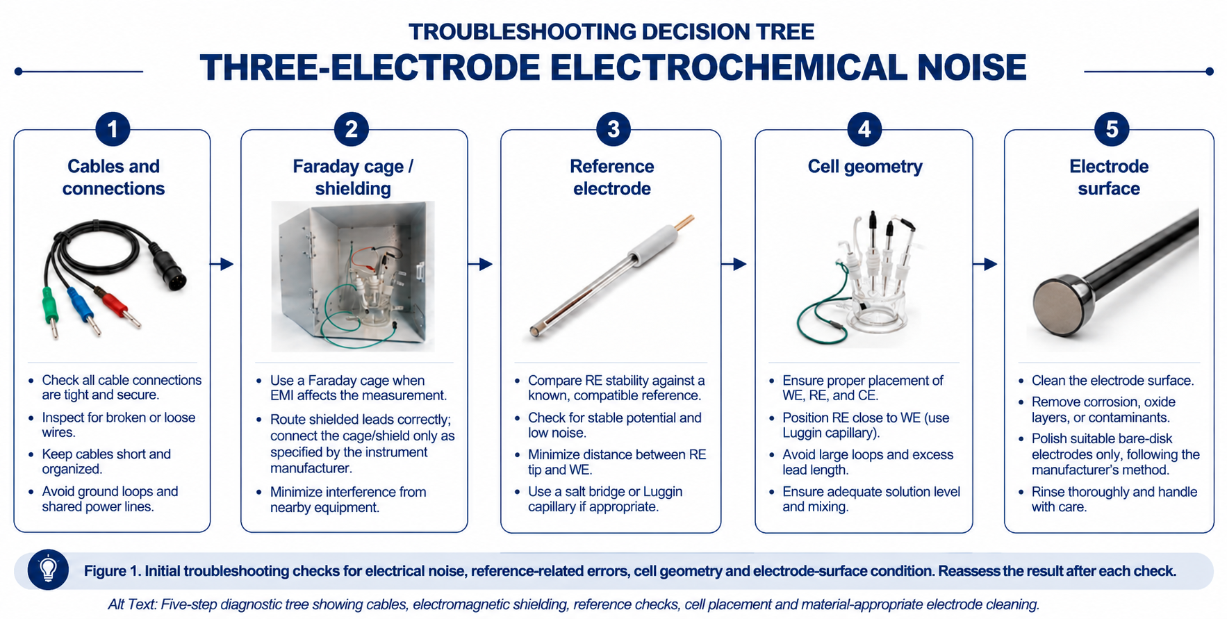
A noisy baseline, a drifting open-circuit potential (OCP) or an unstable reference reading feels like a single vague problem, but the symptoms may have electrical, instrumental or electrochemical origins. A short initial bench check can help separate them before altering the experiment or potentiostat settings. Five useful early checks are: the cables and connectors carrying the signal, the electromagnetic environment around the cell, the reference electrode itself, the geometry of the three-electrode arrangement, and the physical state of the working electrode surface. Also consider electrolyte composition, dissolved gases, temperature and whether the working electrode is genuinely equilibrating at open circuit.
These five causes overlap in their symptoms, which is exactly why working through them in a fixed order, rather than guessing, saves the most time. The sections below take each one in turn, with the bench check that confirms or rules it out.
Start with cables and connections
The pain point: intermittent spikes in current or voltage, a trace that is clean one day and noisy the next with no protocol change, or noise that appears only when you touch or move a cable.
Cables and leads are the least glamorous part of a three-electrode setup and an easily overlooked source of noise. A few mechanisms account for most cable-related problems:
- Loose or corroded connectors. A working electrode, counter electrode or reference electrode lead that is not fully seated introduces a variable contact resistance, which shows up as intermittent spikes or a baseline that shifts when the cable is bumped.
- Leads acting as antennas. Any length of unshielded or poorly routed cable can pick up ambient electromagnetic interference (EMI), and the effect is worse for high-impedance, low-current measurements where the signal itself is small relative to the pickup.
- Ground loops. Unintended connections between the instrument, a nominally floating cell and other grounded equipment can create circulating or leakage currents, including mains-frequency interference. Grounding depends on the instrument topology; never disconnect protective earth to eliminate noise.
- Crossed or bundled leads. Running the working electrode signal lead parallel and close to a power cable, stirrer motor lead or heating mantle cable couples noise directly into the measurement.
Bench checklist: cables and connections
- Reseat every connector at the potentiostat and at the electrode end, checking for corrosion or a loose clip, before assuming the problem is electrochemical.
- Keep signal leads as short as the setup allows, and route them away from power cables, stirrer motors and mains-powered equipment.
- Avoid coiling excess cable length into a loop; large cable loops can increase inductive pickup; manage excess lead length without compromising the manufacturer’s cable arrangement.
- Check the potentiostat manufacturer’s grounding and shielding instructions. Identify unintended cell-to-earth or cage-to-earth connections, but do not remove protective earth or alter safety grounding. A single-point shield connection may help where the instrument design specifies it.
- If noise appears or disappears when you touch a cable, suspect a lead, connector or motion-sensitive cell contact; inspect and test the connection before attributing the disturbance to electrode chemistry.
Ruling out cables first matters because every other fix in this guide costs time or money, and none of them will resolve a problem that a reseated connector would have fixed in under a minute.
Faraday cage and electromagnetic shielding
The pain point: a baseline with a persistent 50 Hz (or 60 Hz) hum, an EIS spectrum with noisy high-frequency phase or magnitude (also check wiring inductance and instrument limits), or noise that gets measurably worse near certain lab equipment (monitors, switching power supplies, pumps).
Why shielding matters more as current gets smaller
Modern labs are full of sources of electromagnetic interference: mains wiring, monitors, switching power supplies, pumps and nearby instruments can all couple interference into leads or the cell, creating fluctuating readings that may resemble baseline drift, and the effect is proportionally worse the smaller your measured current and the higher your cell’s impedance. A Faraday cage works by presenting a continuous conductive enclosure or fine conductive mesh around the cell; external electric fields and many radio-frequency disturbances cause charges to redistribute on the cage surface, creating an equipotential boundary that strongly reduces field penetration into the enclosed volume. In electrochemistry, the practical benefit is reduced capacitive pickup on leads and reduced noise at the cell, which improves the signal-to-noise ratio specifically for low-current and high-impedance experiments such as EIS, microelectrode voltammetry and measurements in low-conductivity electrolytes.
Where a cage helps most
- Electrochemical impedance spectroscopy (EIS): less EMI-related spectral scatter when external pickup is the limiting factor; lead inductance and instrument response still require separate checks.
- Low-current measurements (nanoamp to microamp range): sensors, microelectrode voltammetry, corrosion monitoring and thin-film or coating studies.
- High-impedance systems: low-conductivity electrolytes, small-area electrodes and weak faradaic signals, where the measured current is close to the noise floor.
- Long-duration experiments: less electrically induced baseline variation during long runs; shielding does not prevent real chemical or reference-potential drift.
Getting shielding right, not just present
A cage that is present but poorly used will underperform. Connect the cage or shield only as specified by the potentiostat and cage manufacturers. An unsuitable extra earth connection can increase noise; never defeat protective-earth connections. See Start with cables and connections for cable and grounding checks. Enclose the leads as well as the cell where practical, since cable loops are a common EMI entry point even inside an otherwise well-shielded enclosure, and route gas purge lines, temperature probes or stirrer shafts through the cage in a way that does not leave a large unshielded gap. Be aware that a Faraday cage is primarily effective against electric-field interference and many RF disturbances; low-frequency magnetic interference, such as from a nearby transformer, may need a different mitigation strategy.
The Faraday Cage for Electrochemical Measurements is designed around this real-world use case rather than as a bare enclosure: a bench-friendly standard footprint of 24 × 23 × 30 cm accommodates the cell plus lead routing, with customisable cable-entry and feedthrough styles to suit gas lines, temperature probes or specific cell geometries, and a connection provision for instrument-appropriate shielding. Check enclosure clearance, feedthroughs and the specific potentiostat’s grounding requirements before ordering. It is listed with other electrochemistry accessories.
Reference electrode stability
The pain point: the OCP does not settle to a stable value, drifts steadily over the course of a run, jumps between otherwise identical experiments, or your recorded potentials differ from literature values after considering reference scale, solution conditions and uncompensated resistance.
The two failure modes behind drift
Reference-related errors can arise from the internal half-cell, its filling electrolyte or the liquid junction. Importantly, a drifting OCP can also reflect real changes in working-electrode surface state, dissolved oxygen, pH, temperature or solution composition; it is not proof of reference-electrode failure.
- Junction clogging or contamination. Reference electrodes connect to the working solution through a porous frit or liquid junction. Over time this junction can become clogged or contaminated by the sample, increasing junction impedance or changing the liquid-junction potential, which can destabilise the measured potential. Possible causes include crystallised filling salt, sample-derived precipitates and deposits at the porous junction; the cause depends on the electrode and sample chemistry.
- Filling solution depletion or contamination. The internal filling solution (for example, 3 mol L⁻¹ KCl or saturated KCl for different Ag/AgCl designs) can become depleted, diluted by ingress from the working compartment, or contaminated over time, which can change the half-cell potential and junction potential relative to the stated reference specification.
Diagnosing which one you have
Compare the suspect reference with a well-maintained reference of known type in the same compatible test electrolyte at a controlled temperature. Check the expected potential difference for their exact filling electrolytes and allow junction potentials to stabilise. A persistent offset can arise from filling-electrolyte composition, contamination, junction potentials or a reference-scale mismatch; fluctuating readings can also indicate a blocked junction, bubbles, electrical pickup or a changing test solution. This comparison diagnoses the problem but does not repair a faulty electrode.
Bench checklist for reference electrode maintenance
- Inspect the frit or junction for discolouration or visible deposits, and follow the exact model’s approved rinsing, junction-maintenance or replacement procedure. Avoid improvised chemical cleaning; replace the electrode if its stability cannot be restored.
- For refillable designs, inspect the filling level and maintain it at the frequency and concentration specified for that model. Do not assume every Ag/AgCl electrode uses saturated KCl: some require 3 mol L⁻¹ KCl, while gel-filled or sealed types may not be refillable.
- Follow the manufacturer’s model-specific storage guidance. Many aqueous liquid-junction electrodes require wet storage in a specified electrolyte, but some reference designs have different transport or storage requirements; drying a junction that is meant to remain wet can impair its response.
- Match the reference electrode chemistry to the electrolyte: an aqueous chloride-filled reference can introduce water or chloride into an incompatible or moisture-sensitive sample unless an appropriate bridge and junction design is used.
- Where the sample chemistry is likely to attack or clog a single junction quickly, a double-junction design isolates the reference half-cell from the sample with an intermediate salt bridge, but the outer bridge electrolyte must be compatible with the sample, and additional junction potentials and fouling remain possible.
Choosing the right reference chemistry for your electrolyte
Browse the full range on the reference electrodes page, or match your electrolyte to one of the options below.
- General aqueous work: Ag/AgCl Reference Electrode is a common mercury-free option for compatible aqueous media. Confirm its specified KCl concentration, sample compatibility, temperature and junction design; it is not a universal choice across all pH or electrolyte conditions.
- Chloride-sensitive samples or fast fouling: the Double Salt Bridge Saturated Calomel Electrode provides an additional liquid junction. It can reduce direct chloride crossover only when its outer bridge electrolyte and junction are selected appropriately; it still contains mercury and adds a possible junction-potential contribution. Where mercury or chloride is unacceptable, select a suitable alternative reference design.
- Strongly alkaline electrolytes: Hg/HgO Reference Electrode is an established option for compatible strongly alkaline electrolytes. Its reference potential depends on the specified alkaline filling solution and temperature; mercury handling, contamination control and waste procedures are essential.
- Non-aqueous or organic electrolytes: the Non-aqueous Ag/Ag⁺ Reference Electrode can be used with a compatible, appropriately dry organic filling electrolyte. Verify the solvent, silver-ion and supporting-electrolyte composition; check its potential against a suitable ferrocene/ferrocenium standard under the actual measurement conditions, where chemically appropriate.
- Hydrogen-reference scale for pH-dependent studies: the Reversible Hydrogen Electrode sets the hydrogen equilibrium to 0 V versus RHE at the electrolyte’s pH and specified hydrogen activity. This does not make HER or OER kinetics pH-independent. A practical hydrogen electrode requires an appropriate H₂ system, leak control, ventilation and institutional gas-safety approval.
Cell geometry and electrode spacing
The pain point: onset potentials or apparent Tafel slopes that change with current because of uncompensated resistance, uncompensated resistance that seems implausibly high, or measurements that are not reproducible between two cells that are nominally identical.
Why geometry changes what you measure
Electrode geometry, electrolyte conductivity and reference-tip position affect the uncompensated resistance, Ru, between the working-electrode interface and the reference sensing point. When current flows, the magnitude of the potential error is approximately |i|Ru; its sign depends on the current convention. Uncorrected error can shift apparent onset potentials and distort kinetic slopes. At genuine open circuit there is no imposed cell current, so ordinary iR drop is not the direct explanation for a drifting OCP.
The reference electrode distance rule
A Luggin capillary can bring the reference sensing position closer to the active working-electrode surface without obstructing the current path. A commonly cited starting point for a capillary tip of outer diameter d is a tip-to-active-surface clearance of about 2d. This is a geometry-dependent guideline, not a universal optimum: too close can shield the electrode, whereas too far can increase Ru. Measure Ru when its contribution matters and use only instrument-appropriate compensation to avoid control-loop instability. A J-Type Fritted Luggin Capillary provides a way to position the reference ionic contact. Keep the electrolyte-filled path continuous and free of bubbles; an insulating bubble or blocked frit can make the reference reading unreliable.
Choosing a cell format that matches your geometry needs
Cell volume and shape are not just a convenience question; they constrain electrode placement. Uncompensated resistance also depends strongly on electrolyte conductivity and the current distribution. See the full electrochemical cell range, or for corrosion work the corrosion test electrochemical cells.
- Minimising electrode spacing and solution volume: the Small-Volume Conical Three-Electrode Electrochemical Cell enables work with limited electrolyte volume and may facilitate closer reference positioning. Lower uncompensated resistance is not guaranteed without appropriate conductivity and electrode placement.
- Multi-electrode or multi-probe setups: the 5-Port Electrolytic Cell and its temperature-controlled counterpart, the Jacketed 5-Port Electrolytic Cell, give each electrode, gas line or sampling probe a dedicated, fixed port, which can improve repeatability when electrode immersion depths and tip positions are also controlled.
- General-purpose routine work: the Glass Electrochemical Cell, unsealed offers open access for electrode positioning and cleaning, suited to standard laboratory and teaching use where geometry does not need to be held to tight tolerances.
- Air-sensitive or long-duration studies: the Sealed Electrochemical Cell can hold electrode positions and, when correctly sealed and compatible with the experiment, reduce evaporation and atmospheric gas exchange. Oxygen ingress can alter OCP in oxygen-sensitive systems, but sealing alone cannot eliminate drift from surface transformations or solution chemistry. Provide appropriate venting for gas-evolving or pressurised experiments.
- Temperature-dependent kinetics: the Jacketed Sealed Glass Cell allows temperature control through a circulation jacket. Record the actual solution temperature, because electrolyte conductivity, reference potential and reaction kinetics can change with temperature; a jacket by itself does not prove temperature stability.
For a wider comparison of beaker, sealed, jacketed, H-cell and flow-cell formats, read the ScienceGears electrochemical cell selection guide.
Counter electrode geometry matters too
At a given cell current, a small counter electrode can experience greater local current density and polarisation. This does not automatically shift a properly controlled working-electrode potential; problems arise if counter-electrode polarisation exceeds the potentiostat’s compliance limit, or if counter-reaction products cross over and affect the working compartment. A larger appropriate counter-electrode area can reduce current density, but material stability and separation of counter products also matter. The Platinum Gauze Electrode and Platinum Mesh Electrode can provide greater area than a straight wire for compatible higher-current applications, while the Platinum Wire Electrode can suit lower-current work when its available area is adequate, and the Graphite Rod Counter Electrode may be economical if its stability under the actual anodic or cathodic counter reaction is verified; graphite can corrode and release products in unsuitable conditions. Platinum can also dissolve or form reaction products under some conditions. The full range is on the counter electrodes page, and the counter electrode selection guide compares the options in more depth.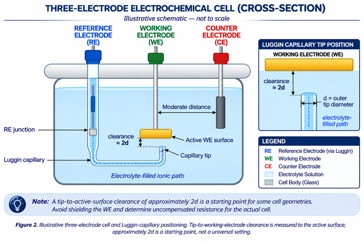
Electrode surface preparation
The pain point: peak currents that decline or peak separations that change between runs, a cyclic voltammogram that looks textbook-clean on day one and progressively worse over a week of reuse, or two nominally identical electrodes giving different baseline currents.
Why surface state drives baseline stability
The working electrode surface is where the reaction of interest happens, and any residue, oxide layer, adsorbed film or physical scratch on that surface changes the effective electron-transfer kinetics and the background (including double-layer charging) current. Other parts of the cell can produce similar symptoms. This is one of the most common causes of poor reproducibility between runs and between users on the same instrument, but cleaning or polishing should follow the electrode material and any surface-coating requirements. Browse the available working electrodes (disc, plate, rod, L-type and carbon paste formats) for material and size options.
The standard polishing sequence
For an unmodified, mechanically polishable disk electrode (for example, many glassy carbon, platinum or gold disks), use the manufacturer’s material-specific cleaning procedure. Often a light fine-alumina polish is sufficient; use coarser abrasives or abrasive paper only when the electrode maker explicitly permits them and the surface requires restoration. Where several grades are justified, progress coarse-to-fine with separate pads and thorough rinsing. Do not abrade screen-printed, coated, microfabricated or otherwise fragile electrodes unless their instructions specifically allow it.
Bench checklist: surface preparation
- Inspect the electrode surface visually before every use; surface damage or an anomalous blank response warrants investigation; repolish only if the electrode design and coating permit it.
- Use a flat, rigid polishing base for uniform contact pressure across the electrode face — an uneven or soft polishing surface undermines the coarse-to-fine sequence even with the right abrasive grades.
- Keep separate pads for each alumina grade and for velvet versus microcloth finishing stages, and rinse the electrode thoroughly with the manufacturer-recommended solvent between steps to prevent cross-contamination of grit sizes.
- A 0.05 µm alumina finish is commonly used for compatible bare disk electrodes, but the final abrasive and cleaning method must follow the electrode supplier’s instructions.
- Run a blank-electrolyte cyclic voltammogram after polishing and before your real experiment; compare the background shape and magnitude with a validated baseline for that specific electrode and electrolyte. A blank CV alone cannot prove surface cleanliness; unusual currents can also arise from dissolved gases, impurities, capacitance or reference instability.
- Handle freshly polished electrodes by the body or holder, not the polished face, and rinse immediately before immersion, since even brief contact with skin or bench surfaces reintroduces the contamination the polish just removed.
An Electrode Polishing Kit sets this workflow up with the full stepwise system in one place: two 100 × 100 mm glass base plates for flat, stable polishing, the three standard alumina grades (1.0, 0.3 and 0.05 µm) at 20 g each, five velvet and five microcloth pads to keep finishing stages separate, and 2000# and 3000# abrasive papers for initial corrective work on stubborn films or scratches. Select the abrasive grade and polishing method to match the particular electrode; not every electrode requires a full coarse-to-fine sequence. For a step-by-step method, see how to polish and maintain glassy carbon, gold and platinum electrodes.
The troubleshooting tree: working through a symptom step by step
Use this sequence when a run goes wrong and you are not yet sure which of the five causes is responsible. These are practical screening checks; more complex reference, chemistry or instrument faults may require longer tests.
- Reseat and inspect all cables and connectors (Start with cables and connections). If gentle movement changes the trace, investigate the lead, clip and any movement-sensitive cell contact.
- Check grounding. Follow the instrument-specific shield and earth-connection diagram; identify unintended ground loops without disconnecting protective earth.
- Enclose the cell and leads in a Faraday cage if you have not already, particularly for EIS, low-current or high-impedance work (Faraday cage and electromagnetic shielding). A reduction in mains-frequency noise supports an EMI explanation, but does not rule out other causes.
- Check the reference electrode against a known standard or a fresh replacement (Reference electrode stability). Account for reference type, filling electrolyte, temperature and junction potential. An offset or drifting comparison can have several causes.
- Verify cell geometry: use the ~2d Luggin clearance only as a starting point measured to the active working-electrode surface; check for bubbles, shielding, electrolyte conductivity and counter-electrode compliance. See Cell geometry and electrode spacing.
- Inspect and, if needed, clean or polish a compatible working-electrode surface (Electrode surface preparation), then repeat an appropriate blank or standard check against the system’s validated baseline before repeating the real experiment.
- If the problem persists after all five checks, evaluate the instrument (current range, bandwidth, filters, lead inductance, reference-input impedance and iR compensation) alongside solution composition, temperature, gas exchange and time-dependent electrode chemistry. Check with a dummy cell where the manufacturer recommends it.
Decision matrix: matching the fix to the failure mode
| Symptom / application | Recommended fix | Specific product | Key rationale | Key constraint |
|---|---|---|---|---|
| Intermittent spikes that change when a cable is touched | Reseat and shorten signal cables | — (bench procedure) | Movement sensitivity suggests a connection or contact fault | Requires physically isolating each connector to confirm |
| Persistent 50/60 Hz hum in the baseline | Faraday cage with instrument-approved shielding | Faraday Cage for Electrochemical Measurements | Conductive enclosure reduces capacitive pickup on leads and cell | Follow instrument grounding instructions; retain protective earth |
| Unstable or noisy EIS spectrum at high frequency | Check lead arrangement; add cage where EMI is identified | Faraday Cage for Electrochemical Measurements | Reduces external pickup when it affects the spectrum | Also assess wiring inductance, low-frequency magnetic pickup and instrument limits |
| Reference potential steady but offset from expected value | Compare reference and service as specified | Ag/AgCl Reference Electrode | Incorrect filling electrolyte, junction potential or temperature can shift the reading | Use the exact model’s specified electrolyte; not always saturated KCl |
| Reference potential will not settle, drifts progressively at open circuit | Inspect/clean/replace junction | Ag/AgCl Reference Electrode | Blocked or contaminated junction is one possible cause of unstable readings | Use approved maintenance method; compare against a known reference |
| Fast-fouling sample chemistry attacking the reference junction | Double-junction reference electrode | Double Salt Bridge Saturated Calomel Electrode | Compatible outer bridge can limit crossover from inner filling electrolyte | Contains mercury; check outer bridge electrolyte and junction potential |
| Strongly alkaline electrolyte, chloride chemistry unsuitable | Hg/HgO reference electrode | Hg/HgO Reference Electrode | Established for compatible alkaline media; potential depends on filling electrolyte | Mercury handling, waste controls and model-specific filling electrolyte required |
| Non-aqueous electrolyte, reference potential drifting with solvent composition | Non-aqueous Ag/Ag⁺ reference electrode | Non-aqueous Ag/Ag⁺ Reference Electrode | Can limit water contamination if correctly prepared and compatible | Check against a suitable Fc/Fc⁺ standard in matching conditions |
| Hydrogen equilibrium reference for HER/OER | Reversible hydrogen electrode | Reversible Hydrogen Electrode | HER equilibrium is 0 V vs RHE at local pH; kinetics may remain pH-dependent | Requires approved H₂ handling, ventilation and leak controls |
| Onset potential or Tafel slope shifting with current density | Reposition reference via Luggin capillary | J-Type Fritted Luggin Capillary | ~2d clearance can be a starting point relative to active WE surface | Check bubbles, shielding and uncompensated resistance |
| Poor reproducibility from improvised electrode positioning | Fixed multi-port cell | 5-Port Electrolytic Cell | Fixed ports help when electrode depths are reproducible | Larger footprint than a simple beaker setup |
| Small sample volume, need minimal electrode spacing | Small-volume conical cell | Small-Volume Conical Three-Electrode Electrochemical Cell | Low-volume geometry can facilitate compact electrode placement | Resistance still depends on conductivity and electrode positioning |
| OCP drifting slowly over long runs, suspected oxygen ingress | Sealed electrochemical cell | Sealed Electrochemical Cell | Can reduce gas exchange and evaporation when properly sealed | Gas-generating cells require safe venting; other OCP drift remains possible |
| Temperature-dependent kinetics or drift resembling electrode instability | Jacketed sealed glass cell | Jacketed Sealed Glass Cell | A controlled jacket can reduce solution-temperature fluctuations | Monitor actual solution temperature and use compatible fluid/tubing |
| Counter polarisation or crossover affecting the WE result | Higher surface area counter electrode | Platinum Gauze Electrode | Area can reduce CE polarisation; monitor compliance and counter products | Check current, material stability, separation and instrument compliance |
| Cost-sensitive counter electrode for compatible reactions | Graphite rod counter electrode | Graphite Rod Counter Electrode | Cost-effective in conditions where graphite stability is demonstrated | Can corrode or release products, especially at anodic potentials |
| Declining peak current or growing background current over repeated runs | Material-appropriate surface cleaning/polishing | Electrode Polishing Kit | Polishing may restore suitable bare-disk surfaces | Not for coated or fragile electrodes; follow the supplier method |
Frequently asked questions
1. How do I tell whether noise is electrical (EMI/cables) or electrochemical (reference electrode) in origin?
Touch and gently move each cable while watching the trace; a response suggests a mechanical connection or movement-sensitive cell problem. If cables check out, run the cell inside a Faraday cage; if a persistent hum or high-frequency instability disappears, external pickup likely contributed, but electrochemical changes can coexist.
2. My OCP was stable last week and is drifting today with no protocol change — what should I check first?
Start with the reference electrode: check it against a fresh replacement or a known standard in a simple test solution. An offset is not diagnostic by itself: check the specified reference electrolyte, junction potential, temperature and contacts. If the reference is stable, investigate genuine working-electrode equilibration, surface chemistry, dissolved oxygen and electrolyte changes. Sealing may help only when atmospheric exchange is the identified cause.
3. Do I need a Faraday cage for every three-electrode experiment?
Not necessarily. If you are working with reasonably large currents in a typical cyclic voltammetry setup, a cage may not be needed. It becomes far more valuable for EIS, low-current (nanoamp to microamp) measurements, electrically noisy or high-impedance cells, and long-duration measurements where electrical pickup masks the signal. It will not correct a genuine changing OCP.
4. How often should I repolish my working electrode?
Investigate departures from a validated blank or standard response, then polish only when the material and electrode construction permit it. Unmodified disk electrodes may need periodic light polishing; never apply that routine automatically to modified films, screen-printed electrodes or fragile surfaces.
5. Can incorrect grounding actually make noise worse rather than better?
Yes. Poor grounding and unintended ground loops can introduce extra noise or instability rather than removing it. Follow the potentiostat’s specified grounding arrangement and avoid unintended extra connections. Never remove protective earth.
6. What is the correct distance for a Luggin capillary from the working electrode?
In some conventional geometries, a spacing of about twice the tip outer diameter (2d) is a useful starting point, measured from the capillary tip to the active working-electrode surface. Positioning it closer risks shielding part of the electrode surface and distorting the current distribution; more distant placement can increase uncompensated resistance. Verify placement experimentally rather than treating 2d as a universal dimension.
More answers are available on the ScienceGears FAQ page.
Expert support: how ScienceGears works alongside your research
Our technical team is led by PhD-trained electrochemists with direct bench experience diagnosing exactly these symptoms across EIS, voltammetry and long-duration corrosion and battery studies, so the guidance you get reflects what actually happens at the connector and the frit, not just a specification sheet. Learn more about ScienceGears.
Before you order
If you are not sure whether your noise or drift problem calls for a Faraday cage, a different reference electrode chemistry, or a change to cell geometry, our technical team will work through your specific setup with you before you commit to a fix. Talk to our technical team →
Noise and drift diagnosis
Send us a description of your trace and we can help you narrow down which of the five causes in this guide is the likely source before you start swapping components at random.
Complete system supply
- Faraday Cage for Electrochemical Measurements
- Reference electrodes
- Counter electrodes
- Electrochemical cells
- J-Type Fritted Luggin Capillary
- Electrode Polishing Kit
Stock and delivery enquiries
Contact ScienceGears to confirm current availability, dispatch timing and delivery options for the required electrode, cage, polishing consumable or cell before planning a time-sensitive experiment.
“Start with simple checks: connections, instrument-approved shielding, reference stability and whether the working-electrode surface is appropriate for the experiment.”
Further reading
- Potentiostats / Galvanostats and how to choose the right potentiostat
- Reference electrodes for precise electrochemical control
- Electrochemical cell: complete guide for research and laboratory applications
- Counter electrodes for three-electrode systems
- Corrosion test electrochemical cells for ASTM-aligned corrosion testing setups
- Application notes, including the Reference Electrode FAQ & Maintenance Guide
Get in touch
If your three-electrode setup has a noisy baseline, a drifting OCP, or a reference electrode you no longer trust, our technical team can help you work through the troubleshooting tree for your specific cell, electrolyte, and current range.