
Table of contents
- Why electrode area sets the quality of your H-cell data
- What typical electrode area means in published H-cell work
- Matching electrode area to current, gas volume and chamber size
- Choosing the counter electrode area and material
- Membrane aperture, solution resistance and reference electrode placement
- A bench protocol for a two-hour water-splitting run
- Adding light or temperature control without changing the area rules
- Where the H-cell stops being the right tool
- Decision matrix for cell format and electrode area
- Frequently asked questions
- Expert support — how ScienceGears works alongside your research
- Further reading and get in touch
1. Why electrode area sets the quality of your H-cell data
A reviewer asks why your oxygen evolution overpotential at 10 mA cm⁻² is 60 mV worse than a paper using the same catalyst, and you realise you cannot say with confidence whether the difference is the catalyst, the electrode, or the cell. This is one source of inter-laboratory disagreement in water-splitting measurements: exposed electrode geometry, cell resistance and counter-electrode selection can all affect the comparison.
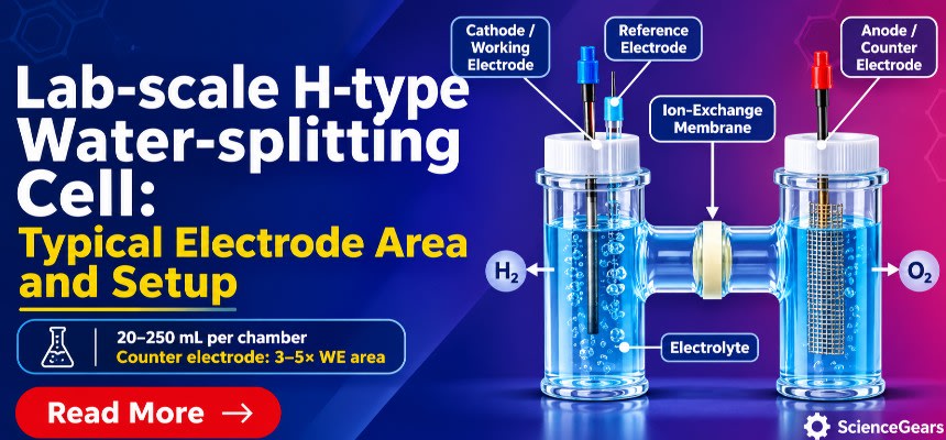
Figure 1. Three-electrode H-type cell for water splitting: electrode layout, membrane aperture and ionic current path
( Schematic of a two-chamber H-cell under three-electrode control. The working electrode (HER) and the reference electrode tip share the left chamber, and the larger mesh counter electrode (OER) sits in the right chamber. An ion-exchange membrane in the central bridge aperture separates the chambers, and the dashed ionic current path passes through it. The bridge aperture and membrane may contribute to whole-cell ohmic losses, whilst the uncompensated working-to-reference resistance also depends on reference placement. Separate H₂ and O₂ outlets reduce direct mixing but cannot rule out gas crossover.)
The problem is not hypothetical. An inter-laboratory study of a standardised nickel–cobalt oxide electrode on a rotating disc in 1 M KOH found a spread of roughly 50 mV at 10 mA cm⁻² between groups, even though everyone followed the same written protocol (Tesch et al., Royal Society of Chemistry open-access article, 2023). If a tightly specified rotating-disc measurement drifts by that much, an H-cell, with its membrane, its two electrolytes and its free-rising bubbles, has even more room to introduce artefacts.
Electrode area matters because it enters every number you will report. Current density is current divided by geometric area, so an error in area is an error in every point on your polarisation curve. At a chosen geometric current density, area sets total current and theoretical gas-generation rate; current, cell geometry, electrolyte transport and counter-electrode material also influence resistive losses, local pH gradients and contamination risk.
An H-cell separates the anodic and cathodic reactions behind an ion-exchange membrane. That separation is what makes it useful for water splitting: hydrogen and oxygen are collected from separate compartments, which can reduce cross-reaction interference but does not eliminate permeation, dissolved-gas crossover or leaks. It is also what makes area decisions less forgiving than in a single-compartment beaker, because the membrane, bridge, ionic conductivity and electrode/reference geometry together influence the cell response.
In this guide the working electrode is always the electrode under study, and the counter electrode is the one that completes the circuit in the other chamber. The reference electrode sits beside the working electrode in the same chamber. That three-electrode arrangement is the one ScienceGears documents for its Jacketed H-Type Membrane Cell, which places the working and reference electrodes in one chamber and the counter electrode in the other.
Where this maps in practice. If you are still choosing a cell format, the H-cell range covers unsealed, sealed, jacketed, PTFE, three-chamber and photoelectrochemical variants, with listed standard capacities commonly spanning 20–250 mL for particular models; options and any custom volumes vary by configuration. The earlier H-cell guide to dual-chamber systems explains the format differences in more detail; this post concentrates on sizing and setup for water splitting specifically.
2. What typical electrode area means in published H-cell work
You open ten water-splitting papers looking for a standard electrode area, and find ten different answers. That is because there is no single standard. What exists is a set of conventions, each tied to a purpose.
The reporting convention is geometric current density. The widely used benchmarking protocol for oxygen and hydrogen evolution catalysts adopts the overpotential needed to reach 10 mA cm⁻², normalised to geometric area, as a common comparison metric, alongside stability and other measurements. The authors chose that current density because it approximates what a 10 % efficient solar-to-fuels device would produce under one sun (McCrory et al., J. Am. Chem. Soc. 2013, 135, 16977; McCrory et al., J. Am. Chem. Soc. 2015, 137, 4347). Whatever area you choose, report geometric current density, and measure that area rather than assuming it.
Rotating-disc benchmarks use small discs. The original protocol used a 5 mm disc, which has a geometric area of about 0.196 cm². Those measurements are done in a single beaker-type cell with rotation to shed bubbles, so they are a reference point, not an H-cell recipe.
H-cell working-electrode dimensions are selected for the particular experiment; there is no literature-wide standard area. For initial bench-scale HER or OER catalyst screening, approximately 0.25–1 cm² of well-defined exposed geometric area is a useful starting range, whilst smaller discs and larger plates, foams or meshes are also used. Do not treat an electrode area reported for CO₂ reduction or another reaction as an established water-splitting convention. The appropriate choice depends on target total current, potentiostat limits, chamber geometry, separator aperture, transport and gas handling.
Mass loading and area are different things. A nanoparticulate film at 0.8 mg cm⁻² reached 10 mA cm⁻² per geometric area at overpotentials of roughly 0.35–0.5 V in alkaline solution (Jung et al., J. Mater. Chem. A 2016, 4, 3068). Loading can affect available active sites, film resistance and gas release, but geometric area, catalyst loading and electrochemically active surface area (ECSA) are different quantities. Double-layer capacitance is a useful comparative proxy; conversion to absolute ECSA requires an appropriate specific capacitance and stated assumptions. Report geometric area, loading and any ECSA estimate separately.
Defining the exposed area properly. Seal the electrode so that only the intended area is wetted. Use a chemically compatible mask or gasket and measure the exposed footprint, for example from calibrated imaging for flat electrodes. Check edge wetting and avoid including inaccessible back faces without defining the basis. Any area error carries directly into geometric current density; do not assume a universal percentage error.
Where this maps in practice. Working electrodes supplied for electrochemistry come in standard geometries that you can mask to a defined area. For three-dimensional substrates such as metal foam electrodes, the geometric footprint and the true surface area are very different, so the handling and pretreatment advice in the metal foam electrodes for electrocatalysis guide is worth reading before you decide what area to report.
3. Matching electrode area to current, gas volume and chamber size
You pick a 4 cm² electrode because it was lying on the bench, run it at 100 mA cm⁻², and discover that the instrument reaches its current or voltage limit, bubbles increasingly obscure the surface, or the gas-handling capacity becomes inadequate. Choose the area from the current you want, not the other way round.
Start with the current your instrument and cell can deliver
Current is simply geometric current density multiplied by area. At 10 mA cm⁻² a 1 cm² electrode draws 10 mA, which is within the current range of many research potentiostats, provided their compliance voltage is adequate. At 100 mA cm⁻² on 4 cm² you need 400 mA, and the required cell-driving voltage can increase because total current raises ohmic losses across the electrolyte, bridge and separator. If your target current exceeds what your potentiostat can drive at the required voltage, you need either a smaller electrode or a current booster. The electrolysis instrument selection guide covers that decision in depth. Always check the exact potentiostat/booster current range, compliance voltage and connection compatibility rather than assuming an area cut-off.
Convert current into gas volume
Faraday's law gives the gas production directly. Hydrogen requires two electrons per molecule and oxygen four, so for ideal, dry gas at 25 °C and 1 atm (24.47 L mol⁻¹), every 1 mA of current produces about 0.456 mL h⁻¹ of hydrogen and 0.228 mL h⁻¹ of oxygen at 100 % Faradaic efficiency.
| Working electrode area | Geometric current density | Current | H₂ evolved (mL h⁻¹) | O₂ evolved (mL h⁻¹) |
|---|---|---|---|---|
| 0.196 cm² (5 mm disc) | 10 mA cm⁻² | 1.96 mA | 0.89 | 0.45 |
| 1 cm² | 10 mA cm⁻² | 10 mA | 4.6 | 2.3 |
| 1 cm² | 50 mA cm⁻² | 50 mA | 22.8 | 11.4 |
| 2 cm² | 50 mA cm⁻² | 100 mA | 45.6 | 22.8 |
| 4 cm² | 100 mA cm⁻² | 400 mA | 182.6 | 91.3 |
Read the gas-production table alongside the actual free headspace and gas-handling circuit. A two-hour hold at 10 mA cm⁻² on a 1 cm² electrode generates approximately 9.1 mL of H₂ and 4.6 mL of O₂, theoretically, in separate compartments at 100 % Faradaic efficiency. At 50 mA cm⁻² on 2 cm², the same duration generates about 91 mL of H₂. Do not close off either gas outlet during electrolysis: even a nominally sealed cell needs an independently routed, suitably vented or pressure-relieved collection arrangement for each gas. Collection volume, not nominal electrolyte capacity, determines whether a gas trap or measuring vessel is adequate.
Check the chamber volume against the charge you will pass
A practical planning check is charge passed, Q = It, alongside electrolyte volume, conductivity, mass transport and ion transport through the separator. At 10 mA for two hours, Q = 72 C, equivalent to approximately 0.746 mmol of electrons (Q/F); at 400 mA for two hours, Q = 2880 C (29.8 mmol of electrons). This electron quantity is not automatically the number of moles of acid or alkali consumed: local proton or hydroxide production/consumption, ion migration and mixing depend on the half-reactions and membrane. Verify pH and electrolyte composition, and increase volume or stirring where gradients or depletion could bias the result.
Leave room for bubbles
Bubbles matter because they can cover active sites, disturb local mass transport and increase the effective resistance of gas-containing electrolyte. The magnitude depends on current density, electrode orientation, wetting, bubble size, stirring and cell geometry; no fixed 10–50 mA cm⁻² window guarantees that most of the surface remains wetted. Record the actual gas-release behaviour, and compare measurements under reproducible hydrodynamic conditions rather than assuming a universal bubble-free regime.
Match chamber capacity to the experiment
ScienceGears H-cells are listed with capacities of 20, 30, 50, 100, 150, 200 and 250 mL. The Sealed H-Cell page describes interchangeable chamber volumes suited to both low-volume screening and longer electrolysis runs, and lists HER and OER catalyst benchmarking under controlled gas atmospheres among its typical uses. As a starting point for a 1 cm² working electrode at 10–50 mA cm⁻², 50 or 100 mL per compartment may be a useful initial option; smaller capacities can conserve electrolyte for low-current work. Check actual liquid fill, working headspace, stirring, sample withdrawal, crossover and continuous gas venting before selecting a vessel.
The jacketed H-cell product description identifies common volume options as 20–250 mL per compartment, but capacity tables and custom configurations may use different conventions. Obtain written confirmation of the selected model’s usable electrolyte volume per compartment, total cell dimensions and separator aperture before using these numbers in a gas-handling or resistance calculation.
Where this maps in practice. For cell formats, compare the Sealed H-Cell with the H-type membrane cell, unsealed depending on whether you need gas-tight collection. For the instrument side, browse potentiostats and galvanostats and current boosters. For a broader view of when an H-cell is the right vessel at all, see the electrochemical cell selection guide.
Figure 2. Faraday’s-law gas evolution rate versus applied current for H₂ and O₂ at 25 °C
( Log–log plot of H₂ and O₂ evolution rate (mL h⁻¹) against current (mA), assuming 100 % Faradaic efficiency at 25 °C and 1 atm. H₂ (2 e⁻ per molecule) is always twice the O₂ rate (4 e⁻ per molecule). The five marked points match the table in this section, from a 0.196 cm² disc at 10 mA cm⁻² (0.89 mL h⁻¹ H₂) to 4 cm² at 100 mA cm⁻² (182.6 mL h⁻¹ H₂). The shaded band marks the 10–50 mA range a 1 cm² electrode draws at 10–50 mA cm⁻², as a visual guide to the corresponding theoretical gas rates, not a guarantee of safe capacity. )
4. Choosing the counter electrode area and material
You switch to a new catalyst, the activity looks suspiciously good after a few hours, and a post-run analysis finds platinum on the working electrode. The counter electrode is one possible contamination source, to be tested rather than assumed.
Why the counter electrode is not a passive wire
The counter electrode carries the same magnitude of current as the working electrode and sustains the complementary half-reaction. When the working electrode evolves hydrogen, the counter electrode is normally driven anodically and should produce oxygen in a suitable water-splitting electrolyte; competing oxidation reactions are possible depending on composition and potential. Counter-electrode selection therefore affects both cell voltage and the risk of dissolution or reaction-product contamination.
Platinum counter electrodes can dissolve under sufficiently oxidising conditions and may introduce trace metal onto a working electrode, causing artificially enhanced apparent HER activity. For example, Ji and co-workers reported interference from noble-metal counter/reference electrodes in photoelectrochemical hydrogen evolution, including migration despite membrane separation (ACS Catal. 2020, 10, 3381–3389, DOI: 10.1021/acscatal.9b04229). A graphite or alternative counter electrode is not automatically safer: its compatibility must be assessed for the specific anodic reaction and electrolyte.
Graphite has its own problem
Do not conclude that graphite solves everything. A 2020 ACS Catalysis study (Ji et al., vol. 10, 10773) found that a graphite counter electrode can evolve carbon monoxide, which poisons platinum working electrodes in the studied platinum system, with near-saturated CO coverage after approximately 50 HER cycles. The same study found that physical separation in an H-type cell substantially reduced that interference under the study conditions.
This is an important reason to separate counter-electrode chemistry during catalyst benchmarking. An H-cell reduces direct contamination and counter-product interference, but its membrane is not a perfect barrier: dissolved species and gases can still cross, and long tests require analytical checks where contamination could change the conclusion.
Alternatives and what the literature supports
A 2022 Scientific Reports study (vol. 12, 9368) examined counter electrode stability during hydrogen evolution in 0.5 M H₂SO₄ for platinum, gold, glassy carbon and titanium mesh, also considering the relative areas of working and counter electrodes, and identified commercial titanium mesh as a low-dissolution alternative under its tested acidic HER conditions; this does not establish universal titanium stability during anodic oxygen evolution. For alkaline work, nickel-based counter electrodes are common practice, though you should verify the choice against your own contamination checks.
Sizing the counter electrode
Counter-electrode sizing is experiment-specific. For many three-electrode half-reaction screening experiments, a practical starting point is a counter electrode with approximately 2–5 times the exposed geometric area of the working electrode, where space and material allow; this is not a standard or a guarantee of low polarisation or dissolution. For mesh or foam, distinguish projected area from the actual accessible surface and verify counter-electrode potential, current distribution, stability and gas release. Position the counter electrode to allow ionic access to the membrane whilst keeping products and electrical contacts clear of the working electrode.
For contamination-sensitive work, compare fresh and used electrolyte and electrodes using suitable element-sensitive or surface techniques when practical (for example, ICP-MS or XPS, selected for the analyte and detection limit). A repeat run with a different counter electrode is a useful control but does not by itself exclude trace dissolution or migration.
Where this maps in practice. ScienceGears lists counter electrodes alongside metal mesh electrodes and metal foam electrodes, which give you high counter electrode area in a small chamber. If you reuse noble-metal or glassy carbon electrodes, the polishing and maintenance guide for glassy carbon, gold and platinum electrodes covers cleaning between runs.
5. Membrane aperture, solution resistance and reference electrode placement
A polarisation curve that appears to worsen at high current can include solution, separator, contact or mass-transport losses as well as electrode kinetics. In a two-electrode water-splitting measurement, the bridge and membrane can make an important contribution to the total cell resistance; in three-electrode measurements, the working-electrode-to-reference uncompensated resistance additionally depends on reference-tip location. These are not identical quantities.
The aperture controls resistance
A 2020 Electrochimica Acta study of two-chamber H-cells (vol. 348, 136291) reported that, for its two-chamber microbial fuel-cell geometry and electrolyte, the connecting-tube dimensions dominated a measured resistance component, contributing around 80 % of internal resistance under the studied conditions. Its observed electrode-size effects are geometry-specific and should not be extrapolated quantitatively to a membrane-separated water-splitting H-cell.
That study used a microbial system rather than a typical strongly conducting water-splitting electrolyte. It supports checking the bridge geometry, but neither the fraction of resistance attributable to the bridge nor the three-electrode uncompensated resistance can be transferred directly. Practical consequences follow.
-
At a fixed geometric current density, increasing working-electrode area raises total current and theoretical gas production; whether total voltage loss increases depends on the resistance and current distribution. Enlarging an electrode does not automatically reduce the separator or narrow-bridge contribution.
-
If the working electrode is small relative to the bridge aperture, current lines, access resistance and local transport can change; the direction and magnitude of the effect are not fixed without geometry or impedance measurements. A small exposed area also requires careful masking and area determination.
Choose exposed working-electrode area and counter-electrode geometry with the separator aperture, electrode spacing, electrolyte conductivity and target current in mind; no fixed electrode-to-aperture ratio is universally optimal. Ask ScienceGears for the aperture diameter or open area, membrane clamping dimensions and cell dimensions for the exact configuration, because these are not fully specified on every public product page.
Place the reference electrode where it measures the working electrode
Keep the reference electrode in the working-electrode chamber, with its tip or Luggin capillary approximately two tip diameters from the exposed face as an initial positioning guide, then optimise for shielding, bubbles and iR losses. Closer than that and the capillary shields part of the surface and distorts the current distribution; much further away and you add uncompensated solution resistance to the measured potential. Keep the tip out of the bubble plume, because a bubble lodged in the tip shows up as random, sharp noise. A reference electrode in the counter-electrode chamber measures the wrong half-cell.
Choice of reference, calibration against the reversible hydrogen electrode and capillary design are covered in the reference electrode potentials cheat sheet and the Luggin capillary guide, so they are not repeated here. State the electrolyte, measured pH (and temperature), reference-electrode identity and calibration/conversion method. Report half-cell potentials on a clearly identified scale (commonly RHE for HER/OER) and full-cell voltage separately.
Measure and compensate the ohmic drop
Measure the uncompensated working-electrode-to-reference resistance (Rᵤ) using an appropriately configured high-frequency impedance measurement or a validated current-interrupt method. When possible, evaluate it at a representative operating condition as well as before the run; an open-circuit value may not represent a gas-evolving electrode. Identify the high-frequency ohmic intercept only when the spectrum and instrument bandwidth support that assignment. Some benchmarking methods employ approximately 85 % positive-feedback iR compensation, but this is not a universal safe setting; follow instrument guidance, avoid oscillation/overcompensation and document any software or post-processing correction. Report the resistance, measurement conditions and the compensation fraction, and distinguish Rᵤ from full two-electrode cell resistance.
Bubble accumulation, temperature and electrolyte changes can alter measured resistance. Reassess it under documented, comparable conditions during or after the stability test rather than assuming that the initial value remains valid.
Membrane choice as an area and resistance decision
Cation-exchange membranes are common in acidic systems and anion-exchange membranes in alkaline systems, but the actual separator must be selected for ion transport, gas crossover, electrolyte compatibility and the cell design. Membranes for the ScienceGears H-cells are user-supplied, and ScienceGears can provide recommendations and sourcing assistance. From the area point of view, two things matter. First, membrane type, thickness and hydration influence resistance and transport; a thinner membrane may reduce ionic resistance but can increase gas crossover under particular conditions. Second, dry-to-wet swelling changes dimensions; follow the exact membrane grade’s conditioning, cutting and assembly instructions, including wet-state dimensions and gasket compression. Grade comparison, dimensions in each hydration state and pretreatment are covered in the Nafion 117 vs 212 vs 115 comparison and the Nafion specifications guide. Check both compartments for leaks with water using a non-pressurising, manufacturer-appropriate procedure before electrolysis.
Where this maps in practice. Ion-exchange membranes and reference electrodes are listed separately, and the electrode clamp and holder range helps you fix the working electrode position repeatably. If you see leakage, crossover or unstable potentials, the H-cell troubleshooting guide walks through the causes.
Figure 3. Reference capillary tip placement in the working-electrode chamber
( Side view of the working-electrode chamber. The reference capillary tip is aimed at the electrode face, about two tip diameters away (typically 2–3 mm for a 1–1.5 mm capillary) and not touching it. It sits low, clear of the rising H₂ bubble plume. The dashed lines show the ohmic current path converging on the membrane aperture. Too close, and the capillary shields the surface. Too far, and extra uncompensated resistance enters the measured potential. )
6. A bench protocol for a two-hour water-splitting run
You assemble everything correctly, then run a protocol you improvised and cannot reproduce next week. The sequence is an illustrative adaptation of common benchmarking practices, not a validated standard operating procedure for every catalyst, cell or potentiostat.
Before you start
-
Electrolyte. Literature examples include 1 M KOH or NaOH for alkaline work and 0.5 M H₂SO₄ for acidic work. Select electrolyte composition for the catalyst, membrane, reference electrode and institutional procedure; these solutions are not interchangeable. Prepare corrosive solutions with suitable PPE, splash controls and SDS-based precautions, using consistent documented electrolyte batches and compositions in both chambers unless the experiment specifies otherwise.
-
Electrode area. Seal the working electrode and measure the exposed area, as described in section 2.
-
Cell and membrane. Clean the glassware, then condition the membrane according to grade-specific manufacturer instructions; consult the H-cell guide and the Nafion guides linked in section 5 as background rather than a universal pretreatment for anion-exchange membranes.
Assembly and checks
-
Mount the correctly conditioned membrane with compatible gaskets and even compression; perform a non-pressurised water leak check. Fill both chambers to appropriate, documented levels to minimise unwanted hydrostatic transfer.
-
Mount the working and reference electrodes in one chamber and the counter electrode in the other, with the reference tip placed as in section 5.
-
If a defined starting atmosphere is necessary, purge each compartment separately using an approved inert-gas procedure and independently routed exhausts. A 20–30 minute purge may be a starting estimate only after validating flow, volume and oxygen exclusion. Never combine H₂ and O₂ outlet streams or block them; purge gas can also dilute collected product and must be accounted for in Faradaic-efficiency calculations. Check gas-line routing and local ventilation before energising the cell.
-
Record the open circuit potential for 5–10 minutes and confirm it is stable.
-
Measure the working-to-reference uncompensated resistance by a validated method, recording the bias and comparing with values near operating conditions when practicable.
Conditioning, activity and stability
-
Condition the catalyst only within a potential window and cycle range known to be compatible with its composition, substrate and electrolyte. If cyclic conditioning is appropriate, record the number of cycles, scan rate and acceptance criterion for a reproducible state; do not assume that 10–20 cycles at 50–100 mV s⁻¹ are universally non-destructive.
-
Record activity using an LSV scan rate appropriate to the reaction, transport and charging currents; 10 mV s⁻¹ is one common screening choice, not a universal steady-state condition. State the reference scale and assess the influence of uncompensated resistance using a verified correction procedure rather than applying 85 % automatically. Report the potential or overpotential at 10 mA cm⁻² geometric where relevant, and consider stabilised current steps for a steady-state comparison.
-
Hold for stability. Apply a constant 10 mA cm⁻² geometric for two hours and record the potential. A two-hour hold provides only a short-term stability check; it does not demonstrate long-term durability or establish comparability without matching electrolyte, electrodes, potential control and reporting conditions.
-
Re-measure the resistance at open circuit after the hold and compare it with the initial value.
-
Estimate double-layer capacitance using a series of cyclic voltammograms in a genuinely non-Faradaic potential window, with several scan rates and stated fit conditions. Any ECSA calculated from Cdl requires an appropriate material-dependent specific capacitance and carries uncertainty; geometric-normalised activity and capacitance-normalised comparisons should be reported as distinct metrics.
Faradaic efficiency
Faradaic efficiency (FE) checks the fraction of charge leading to the quantified gas product: FE(H₂) = 2Fn(H₂)/Q and FE(O₂) = 4Fn(O₂)/Q, where Q is the integrated charge and n is the measured amount in moles. For a cell equipped with verified, independent gas-collection lines, quantify the appropriate outlet by a calibrated volume method or gas chromatography. Correct measured volumes for temperature, pressure, water vapour and collection losses where applicable, and consider dissolved gas, crossover, leaks and background purge flow. An approximately 2:1 H₂:O₂ molar ratio alone does not prove 100 % FE or gas purity. Keep outlets vented through a laboratory-approved gas-handling system rather than trapping gas in a closed chamber.
What to report
State the electrolyte and measured pH, reference electrode and conversion, exposed geometric area and how you measured it, counter electrode material and area, membrane type and pretreatment, uncompensated resistance and compensation fraction, the potential at 10 mA cm⁻², the stability trace, the method and assumptions for any ECSA estimate, gas-collection conditions and separately measured gas Faradaic efficiencies where reported. Include operating temperature and the distinction between the working-electrode potential and total cell voltage. That list is what lets another group reproduce your number.
Overall water splitting in two-electrode mode
After characterising each half-reaction, the cell may also be operated in two-electrode overall-water-splitting mode if both electrodes, the separator and gas-handling hardware are compatible. The same total current passes through anode and cathode, but each has its own geometric current density (j(anode) = I/A(anode) and j(cathode) = I/A(cathode)); equal areas simplify comparison but are not mandatory. A 2–5× auxiliary-electrode area guideline for three-electrode screening must not be treated as a rule for a two-electrode device. As a hypothetical calculation, two 2 × 2 cm² electrodes operating at 10 mA cm⁻² each pass 40 mA, giving about 18.3 mL h⁻¹ H₂ and 9.1 mL h⁻¹ O₂ at 25 °C, 1 atm and 100 % FE. Even with 10 mL of electrolyte per compartment, independently managed gas outlets and safe venting are essential. Report the measured full-cell voltage, the current and both electrode area bases; one reference electrode can monitor one half-cell, but assigning separate anode/cathode losses requires correctly placed references and allowance for uncompensated potential drops.
Where this maps in practice. The Sealed H-Cell and the Absolutely Sealed Gas-Tight Replaceable Membrane H-Cell can support gas analysis or collection when fitted with separately routed, leak-tested outlets and a suitable venting system, whilst the PTFE H-Type Membrane Electrolytic Cell suits aggressive electrolytes; if you plan very hot or highly oxidising media, confirm seal and O-ring compatibility with ScienceGears before extended runs. The H-cell troubleshooting guide is the natural companion once the protocol is running. If the three-electrode wiring itself is new to your group, start with the potentiostat setup guide.
7. Adding light or temperature control without changing the area rules
Your photoanode behaves differently every afternoon, and you eventually realise the laboratory temperature has drifted by several degrees and the illuminated spot is not the same size as the electrode. Light and temperature add variables, but the area rules from earlier sections still apply.
Temperature
Reaction kinetics, gas solubility and membrane conductivity all depend on temperature. The Jacketed H-Type Membrane Cell places a water-circulation jacket around each compartment, connected to an external recirculating chiller or heater, so both compartments can be temperature-controlled; measure actual electrolyte temperature for quantitative kinetic comparisons. ScienceGears guidance describes indicative temperature stability, tubing connections and circulation requirements; those general engineering considerations are discussed in the ScienceGears dual-chamber guide but are not specifications for every cell and circulator combination; confirm limits and connections for your configuration.
For activation-energy work, hold the electrode area, counter electrode, and membrane fixed, change only the bath temperature, wait for thermal equilibrium at each setpoint, and re-measure the uncompensated resistance at each temperature because it can change as temperature and electrolyte properties change.
Light
For photoelectrochemical water splitting, record the exposed geometric electrode area and the illuminated area separately; optical-to-chemical efficiency calculations also require the actual incident optical power and relevant product yield. Some ScienceGears photoelectrochemical H-cell models list a removable 24 mm diameter quartz window, but this is a model-specific dimension, not a property of every H-cell. The effective illuminated spot is set by optical alignment, beam profile, window opening and geometry, not automatically by the nominal window diameter. If uniform illumination of the entire electrochemically active region is required, mask the photoelectrode accordingly and report the area basis. Dark or partly illuminated regions may still carry electrochemical current and should not be assumed inactive.
Bubbles matter more under illumination. A 2022 Sustainable Energy & Fuels study (Bhanawat, Zhu and Pilon, DOI 10.1039/d1se01730f) simulated bubbles of 0.25–1.75 mm diameter covering up to 78.5 % of the projected surface and found that coverage reduces the photon flux absorbed by the photoelectrode. Keep photocurrent densities moderate and orient the electrode so that bubbles leave the illuminated face.
Where this maps in practice. Choose between the H type Sealed Jacketed Photoelectrochemical cell for gas-tight, temperature-controlled work and the H-Type 3-Port Jacketed Photoelectrochemical Cell with Quartz Window, which provides a three-port configuration for reference placement, gas sampling or electrolyte handling, subject to the supplied port layout. The wider photoelectrochemical cells category lists the other windowed variants.
8. Where the H-cell stops being the right tool
You scale a promising catalyst up to 4 cm² and 200 mA cm⁻² in your H-cell and the results are worse than at 1 cm² and 10 mA cm⁻². Changes in mass transport, bubbles, ohmic losses or current distribution could be responsible; the catalyst alone cannot be blamed without controls.
An H-cell is a screening and diagnostic tool. It is excellent for catalyst ranking, membrane crossover studies, Faradaic efficiency and short-term stability, and it is limited by the membrane aperture, by bubble blanketing, and by gas and electrolyte mass transport at higher current. The ScienceGears dual-chamber guide makes the same distinction: H-cells suit initial screening and fundamental work, whilst flow cells suit high current density and long-term testing. There is no universal cut-off at 100 mA cm⁻² or 100 hours: move to a flow cell or a purpose-built test station when the relevant current, duration, pressure, gas management or transport conditions exceed what your particular H-cell can reproduce and measure reliably.
For device-relevant benchmarking or industrially comparable operation, consider a suitable electrolyser test station with the applicable flow, temperature, pressure and gas-safety controls. The electrolyser test stations cover proton exchange membrane, anion exchange membrane, alkaline, solid oxide and combined configurations.
Related but outside scope
The following are adjacent to this guide but not covered in it: membrane electrode assembly and zero-gap electrolyser testing, gas diffusion electrode flow cells, and powder photocatalyst suspensions. They follow different area and setup conventions, because current distribution, mass transport and ohmic drop are controlled by compression, flow fields and illumination geometry rather than by an aperture in a glass bridge.
Where this maps in practice. The electrolyser test station guide for Australian researchers explains how to choose between the platforms, whilst the electrochemical cell selection guide compares beaker, sealed, jacketed, H-cell and flow cell formats, and the three-chamber H-cell extends the divided-cell idea to experiments with an intermediate compartment.
9. Decision matrix for cell format and electrode area
Use this table as a starting point and adjust it for your electrolyte, current and instrument. The electrode areas are practical starting ranges from the sections above, not specifications.
| Application | Recommended configuration (typical working electrode area) | Specific product | Key rationale | Key constraint |
|---|---|---|---|---|
| Catalyst ranking at 10 mA cm⁻², alkaline | Sealed glass H-cell, 0.25–1 cm² | Sealed H-Cell | Sealed design can support separate sampling; verify independent gas ports and approved gas handling | Confirm membrane aperture before ordering |
| Quick method development or teaching | Open glass H-cell, 0.25–1 cm² | H-type membrane cell, unsealed | Open access for fast electrode changes and intervention | No gas-tight collection |
| Faradaic efficiency by gas collection | Gas-tight cell with replaceable membrane, 1–2 cm² | Absolutely Sealed Gas-Tight Replaceable Membrane H-Cell | Separate outlets facilitate quantification; measure crossover, leakage and gas-collection losses | Independently vent or safely collect H₂ and O₂ at any gas-evolving current; never dead-end outlets |
| Temperature-dependent kinetics | Jacketed glass H-cell, 0.25–1 cm² | Jacketed H-Type Membrane Cell | Jackets allow temperature control; measure the actual electrolyte temperature | Needs an external circulator |
| Concentrated acid, base or oxidising media | PTFE H-cell, 0.25–1 cm² | PTFE H-Type Membrane Electrolytic Cell | PTFE body has broad chemical resistance; whole assembly compatibility must be checked | Opaque; confirm seal compatibility for hot media |
| Solar water splitting, sealed and thermostatted | Windowed jacketed H-cell, electrode inside window | H type Sealed Jacketed Photoelectrochemical cell | Quartz window, gas-tight, temperature control | Record exposed and illuminated areas; mask when uniform illumination is required |
| Photoelectrode work needing extra ports | Windowed cell with additional ports | H-Type 3-Port Jacketed Photoelectrochemical Cell with Quartz Window | Three-port layout provides access options subject to exact port configuration | Typical 24 mm window limits spot size |
| Experiments needing an intermediate compartment | Triple-chamber cell, 0.25–1 cm² | Three-Chamber H-Cell | Separates anode, cathode and middle zone | Two membranes add resistance |
| Foam or porous electrode catalysts | Sealed H-cell with mesh or foam counter electrode | Metal foam electrodes | High surface in a compact footprint | Geometric and true area differ greatly |
| High counter electrode area in small chambers | Mesh counter electrode; approximately 2–5× area is one initial screening option | Metal mesh electrodes | May reduce counter-electrode polarisation if accessible area is sufficient | Choose material for the electrolyte |
| Reference measurement in alkaline or acid | Reference electrode matched to electrolyte | Reference electrodes | Correct potential scale, convertible to RHE | Place tip beside the working electrode |
| Defined working electrode substrate | Masked disc or plate of known area | Working electrodes | Known geometry for area-normalised reporting | Mask and measure exposed area |
| Membrane selection for acid or alkaline | Cation or anion exchange membrane | Ion-exchange membranes | Sets crossover and conductivity | Follow grade-specific conditioning and membrane-compatibility instructions |
| Currents beyond potentiostat limits | Current booster with the same cell | Current boosters | May extend current range when the booster and potentiostat are compatible | Confirm bridge, membrane, gas handling and instrument compliance |
| Reproducible electrode position | Clamp or holder fixed to the cell | Electrode clamp and holder | Repeatable reference and working electrode geometry | Keep tip clear of bubble stream |
| Device-relevant high-current or long-duration validation | Electrolyser test station | Electrolyser test stations | Controls flow, temperature and pressure | Different area conventions apply |
10. Frequently asked questions
What is a typical working electrode area for an H-type water-splitting cell?
There is no single standard, but about 0.25–1 cm² of exposed geometric area is a practical starting range for some lab-scale catalyst screening, not a standard or a universal survey of publications, with rotating-disc benchmarks using a 5 mm disc of about 0.196 cm². Choose the area from the current you intend to pass (see section 3) and the membrane aperture (see section 5), then measure the exposed area rather than assuming it.
Why is 10 mA cm⁻² used as the benchmark current density?
The benchmarking protocol adopts the overpotential needed to reach 10 mA cm⁻² per geometric area because that is roughly the current density expected from a 10 % efficient solar-to-fuels device under one sun. It gives groups a common comparison point, provided each group reports geometric area honestly and states how much ohmic drop was compensated.
Should the counter electrode be platinum or graphite?
Neither is free of artefacts. Platinum can dissolve and redeposit on the working electrode, enhancing apparent activity, and graphite can evolve carbon monoxide that poisons platinum catalysts. Separating the counter electrode with a compatible membrane can reduce, but not eliminate, crossover or dissolved-metal contamination; titanium or nickel mesh are alternatives only after checking the actual anodic conditions and electrolyte. Run a contamination check whichever material you pick.
How large should the counter electrode be compared with the working electrode?
As bench practice, not a published standard, use a counter electrode with approximately 2–5 times the exposed geometric working-electrode area as an initial option, then verify counter-electrode polarisation, dissolution and gas handling rather than assuming the area ratio makes it stable. Mesh or foam geometries give that area in a small chamber, and the electrode should face the membrane aperture.
How much gas will my electrode produce?
Every 1 mA of current gives about 0.456 mL h⁻¹ of hydrogen and 0.228 mL h⁻¹ of oxygen at 25 °C and 1 atm, assuming 100 % Faradaic efficiency. A 1 cm² electrode at 10 mA cm⁻² therefore produces about 4.6 mL h⁻¹ of hydrogen, which matters for headspace, venting and gas-collection design.
When should I move from an H-cell to a flow cell or test station?
Consider moving when required current, duration, control of flow/pressure or device-relevant operation exceeds the verified capability of the chosen H-cell; 100 mA cm⁻² and 100 hours are not universal limits. The H-cell remains the right tool for catalyst screening, membrane crossover, Faradaic efficiency and short stability tests, after which a flow cell or electrolyser test station validates scale-up behaviour.
11. Expert support — how ScienceGears works alongside your research
ScienceGears provides technical assistance with electrochemical cells, electrode sizing and the selection of compatible accessories. For model-dependent questions such as aperture dimensions, sealing materials and membrane compatibility, request the exact configuration details and relevant manufacturer literature before use.
Electrode area and cell sizing review Before you order, send us your target current, electrolyte, electrode material and area, and the potentiostat you plan to use. The technical team will check the numbers against chamber volume, gas production and ohmic drop, and suggest a cell format and counter electrode that fit. Talk to our technical team →
Counter electrode contamination diagnosis If your activity is drifting, improving unexpectedly, or not reproducing between runs, we can walk through your counter electrode choice, membrane condition and electrolyte handling to identify the likely source of contamination or crossover.
Complete system supply
Local availability and dispatch lead times — Stock and shipping dates depend on the specific H-cell model, membrane, electrodes and accessories. Confirm current Australian availability and an agreed dispatch date with ScienceGears before scheduling a time-critical measurement.
"A water-splitting number is only as good as the electrode area, the counter electrode and the aperture behind it, so fix those three before you trust the curve." — ScienceGears Technical Team
12. Further reading and get in touch
Further reading on the ScienceGears blog
-
H-cell electrochemical reactors: complete guide to dual-chamber systems
-
H-cell troubleshooting: membrane leakage, crossover, gas bubbles and reference electrode placement
-
-
High-current electrolysis testing: potentiostat, booster or test station
-
-
How to polish and maintain glassy carbon, gold and platinum electrodes
-
Reference electrode potentials versus SHE: conversion cheat sheet
-
-
Nafion 117 vs 212 vs 115: which grade is right for your experiment
-
-
Product pages mentioned
H-cell range · Photoelectrochemical cells · Metal mesh electrodes · Electrode clamp and holder
Peer-reviewed references cited
-
McCrory, C. C. L.; Jung, S.; Peters, J. C.; Jaramillo, T. F. J. Am. Chem. Soc. 2013, 135, 16977.
-
McCrory, C. C. L.; Jung, S.; Ferrer, I. M.; Chatman, S. M.; Peters, J. C.; Jaramillo, T. F. J. Am. Chem. Soc. 2015, 137, 4347.
-
Jung, S.; McCrory, C. C. L.; Ferrer, I. M.; Peters, J. C.; Jaramillo, T. F. J. Mater. Chem. A 2016, 4, 3068.
-
Tesch, M. F.; Neugebauer, S.; Narangoda, P. V.; Schlögl, R.; Mechler, A. K. Energy Adv. 2023, 2, 1823–1830. DOI: 10.1039/D3YA00340J.
-
Ji, S. G.; Kim, H.; Choi, H.; Lee, S.; Choi, C. H. ACS Catal. 2020, 10, 3381–3389. DOI: 10.1021/acscatal.9b04229.
-
Ji, S. G.; Kim, H.; Park, C.; Kim, W.; Choi, C. H. ACS Catal. 2020, 10, 10773–10783. DOI: 10.1021/acscatal.0c01783.
-
Hasan, M. M.; Allam, N. K. Sci. Rep. 2022, 12, 9368. DOI: 10.1038/s41598-022-13385-w.
-
Rossi, R.; Logan, B. E. Electrochim. Acta 2020, 348, 136291. DOI: 10.1016/j.electacta.2020.136291.
-
Bhanawat, A.; Zhu, K.; Pilon, L. Sustain. Energy Fuels 2022, 6, 910–924. DOI: 10.1039/D1SE01730F.
-
Wang, C. R.; et al. Chem. Rev. 2025, 125, 1257–1302. DOI: 10.1021/acs.chemrev.3c00904 (gas crossover and membrane resistance).
Get in touch
Tell us your electrode area, target current density and electrolyte, and we will help you choose a cell, counter electrode and membrane.